1 The connector specifications
A. Camera Link connector: SDR (3M) or equivalent
Caution: This product is not PoCL type. Only apply 12Vdc power through the power/IO connector.
B. Power/IO connector: HR10A-7R-6PB (Hirose) or equivalent
This connector is for a 12Vdc power input and the input and output signals.
Trigger input signal can be assigned through the camera setting communication.
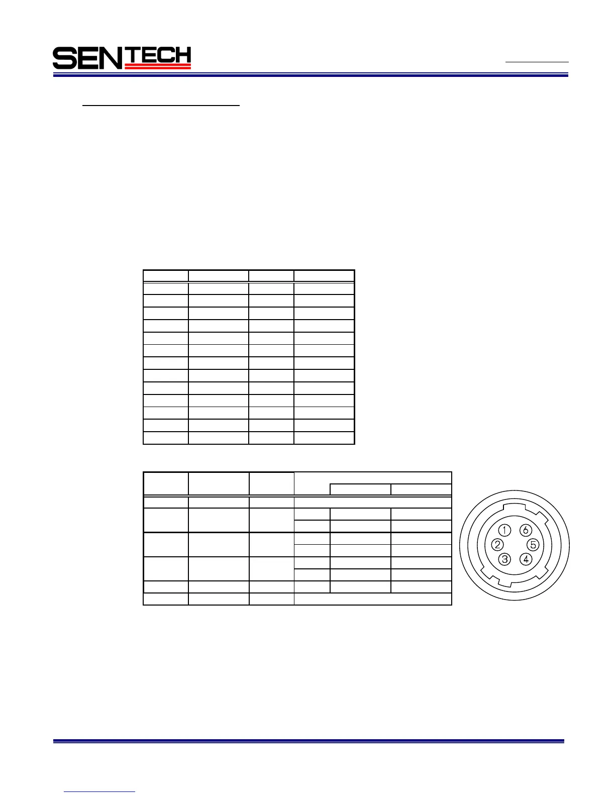
1.1 Pin assignment
A. Camera Link Connector
B. Power/IO Connector
Notes:
Trigger input signal can be assigned either on Camera Link connector (CC1) or on the No. 2 pin of the power/IO
connector through the camera setting communication.
1 GND IN
2 I/O-1 IN/OUT IN 0 to +0.99V
+2.3 to +3.3V
OUT 0V +3.3V
3 I/O-2 IN/OUT IN 0 to +0.99V
+2.3 to +3.3V
OUT 0V +3.3V
4 I/O-3 IN/OUT IN 0 to +0.99V
+2.3 to +3.3V
OUT 0V +3.3V
5 TRG OUT OUT OUT 0V +3.3V
6 +12Vdc IN
0V
+12Vdc
Pin No. Signal name IN/OUT Voltage