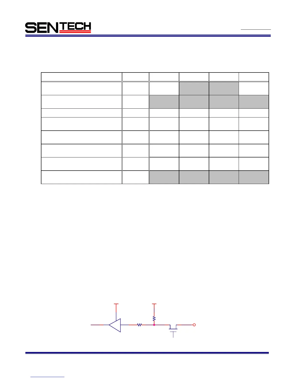
1.2 The signals of the power/IO connector
The input and output signals of the power/IO connector can be change through the camera setting
communication.
The input and output signals of the power/IO connector can be change through the camera setting
communication.
Note.1: Please change “F0H” address data of the register when change the signals of the power/IO connector.
Please change “C0H” address data of the EEPROM when save the signals of the power/IO connector
setting.
“F0H” address data could not save to the EEPROM.
Note.2: Output trigger signal has below delay from the trigger signal input:
30CLK (Approximately 470 useconds)
Note.3: Please change “12H.5” when use the trigger signal input from the power/IO connector.
Note.4: The exposure time is “High” while the camera exposures.
1.3 The equivalent circuit for the input pin of the power/IO connector
+3.3V +3.3V
TC7WH241FK
TOSHIBA
TRIGGER IN
10kohm
100ohm
On resister Max. = 30ohm