Motor Head Unit InstallationMotor Head Unit Installation
LISH
E
N
G
19
6
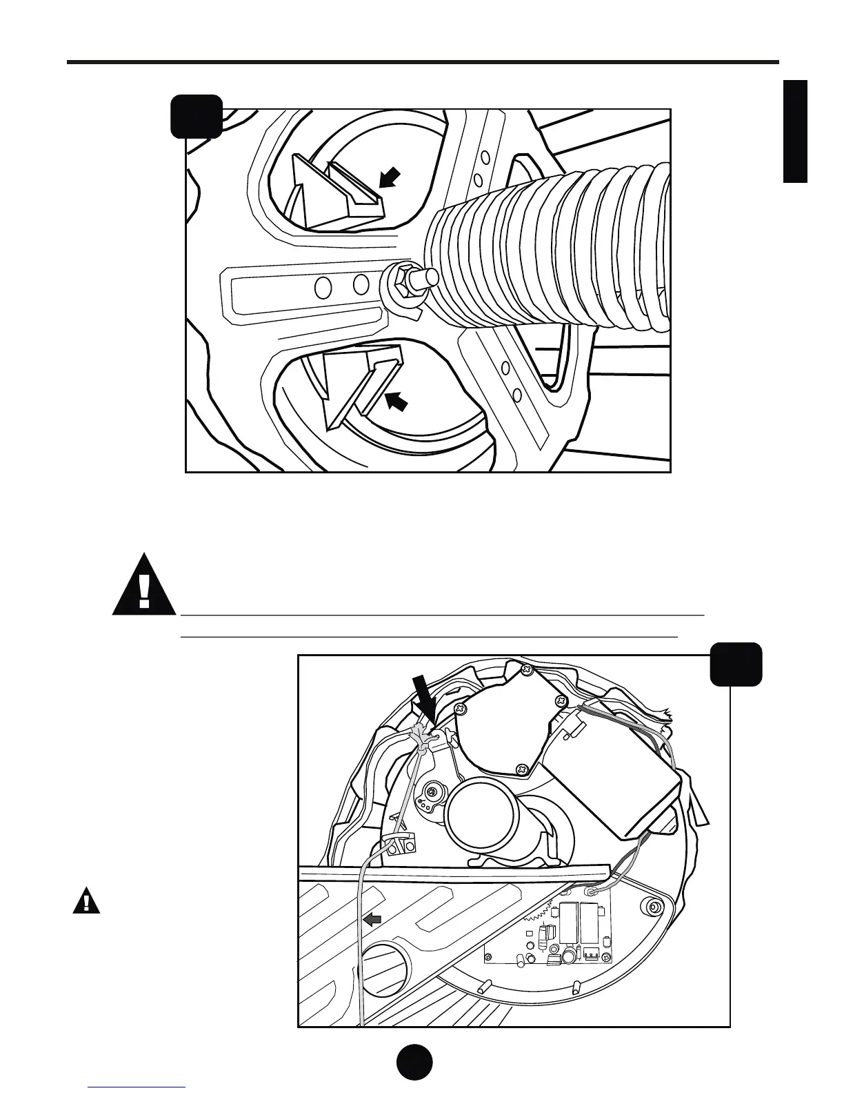
Looking at the opposite side of the motor, that is, from the driving wheel side,
ensure that both drive hooks fit snugly as shown in the above diagram.
The maximum amount of clearance between the surfaces of the
spool wheel and the drive hooks is approximately 1.5mm.
Too much free play on either or both drive hooks, will cause
product malfunction (false collisions and stopping short)
7
Reposition the tube, as
shown here, on the
platform, ensuring it is in
the same position when
you removed it originally.
Attach the supplied release
lanyard to the release pawl
and route the nylon lanyard
as shown in this diagram.
Caution: ensure the
release lanyard is clear of
the door curtain edge at
all times. Route the cord
in a manner that is kept
clear of the door curtain.
Release LanyardRelease Lanyard