3.4 Hydraulic installation
All seals must be in place to protect the operator and anybody else in the
area against an escape of high oil pressure.
WARNING
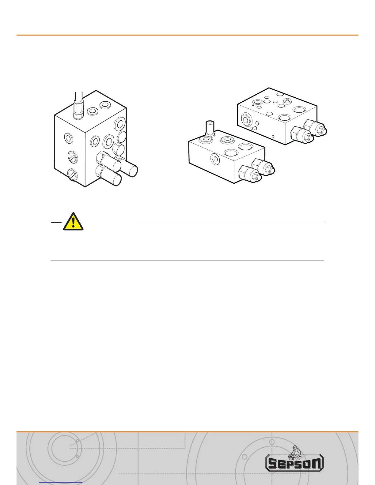
Auto 2-speed block Single speed block
M
V1
V2
1. Connect the directional control valve and the winch by the ports V1 and V2 on
the hydraulic block.
2. Inspect and test all tubing, hoses and connection points for oil leakage.
If the directional control valve is attached to the winch, connect the pressure
hose/tube to the pressure inlet and the return hose/tube to the oil outlet on the
control valve.
For a hydraulic system with xed pump the directional control valve must have an
open centre; otherwise the winch safety brake will not operate properly or not at all.
If a load sensing hydraulic system is used contact Sepson for advice on choice of
control valve.
Make sure that the hydraulic system is set to not deliver higher oil pressure and oil
ow than listed in the technical information section for the winch.
Installation