Do you have a question about the SEPTENTRIO AsteRx-m2 and is the answer not in the manual?
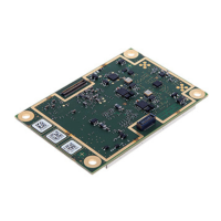
Details mounting holes, M3 screws, spacers, and grounding connections for the OEM module.
Specifies operational temperature range (-40 to +85 °C) and storage temperature range (-55 to +85 °C).
Covers 3.3V power supply via 30-pin connector and power consumption based on GNSS signals.
Explains receiver RF signal input via ANTA/ANTB u.FL connectors and antenna selection logic.
Lists electrical specs like antenna supply voltage, impedance, current limits, noise figure, and VSWR.
Provides formulas for calculating system noise figure (NFsys) and C/N0 based on signal parameters.
Describes the 30-pin main and 60-pin auxiliary connectors, including pin functions and warnings.
Details the pinout for the 30-pin connector, covering power, USB, serial ports, and event inputs.
Details the pinout for the 60-pin connector, including GPIO, Ethernet, and reference inputs.
Explains using an external 10 MHz signal via pin 60 of the 60-pin connector for frequency synchronization.
Describes EventA/EventB inputs for timing external events and synchronizing the receiver's time base with 1PPS signals.
Details GP1 and GP2 pins as programmable LVTTL digital outputs with a max drive current of 10mA.
Explains two methods to enter standby mode: driving nPDN pin low or using the 'exePowerMode, StandBy' command.
Covers using an external SD memory card for logging, compatibility up to 32GB, and FAT32 file system.
Details configuring the USB device interface for USB 1.1 (full speed) or USB 2.0 (high speed) modes.
Describes the receiver's 10/100 Base-T Ethernet support via the RMII interface on the 60-pin connector.
Describes header pitches: 2.54mm for most, 2mm for J500 (PPS/EVENTS) and J501 (GP).
Explains powering via USB Dev (4.5-5.5V) or POWER connector (5-36V), recommending specific USB cables.
States antennas connect directly to OEM board u.FL connectors; explains Vant jumper for 5V or 3.3V.
Details DevKit status LEDs (POWER, GPLED, LOGLED) and 3.3V GP1/GP2 outputs on J501 header.
Describes four COM ports routed to DB9 connectors, conforming to RS232, with RTS/CTS on COM2/COM3.
Explains PPSout signal from J500 header and EVENTA/EVENTB inputs via a buffer.
States DevKit supports 10/100 Base-T Ethernet but cannot be powered through the Ethernet connector.
Describes the USB Dev connector for powering the DevKit and communicating with the receiver over USB.
This section is marked as 'Reserved'.
Explains the REF IN connector for an external 10 MHz frequency reference input, detailing impedance and level.
Details the nRST and LOGGING buttons for resetting the receiver and controlling logging, also connected to 2-pin headers.
Indicates the micro SD card socket on the DevKit for logging files, referencing section 2.10 for details.
| Receiver Type | Multi-frequency GNSS Receiver |
|---|---|
| Supported GNSS | GPS, GLONASS, Galileo, BeiDou, QZSS, SBAS |
| Update Rate | up to 100 Hz |
| Velocity Accuracy | 0.03 m/s |
| Timing Accuracy (RMS) | 20 ns |
| Operating Temperature | -40°C to +85°C |
| Frequency Bands | L1, L2, L5 |
| Heading Accuracy | 0.1 degrees |
| Input Voltage | 9-36 V DC |
| Power Supply | DC |
| Interfaces | Ethernet, USB |
| Protocols | NMEA |
| Position Accuracy (RMS) | 1 cm + 1 ppm |