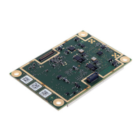
AsteRx-m2 OEM
7
2.1 Mounting
The four mounting holes are compatible with M3 screws. Use M3 3.5mm spacers. An
example of applicable SMD spacer is THF-1.6-3.5-M3 from MAC8.
All mounting holes are grounded, and should preferably be connected to ground on the
host PCB. Note however that the mounting holes should not be relied on as only ground
return connection: a proper ground should be supplied to the GND pins of the I/O
connector(s) as well.
2.2 Environmental
Operational: -40 to +85 °C
Storage: -55 to +85 °C
2.3 Power and Power Consumption
The board is powered through pin#1 and pin#2 of the 30-pin connector. Power supply
voltage must be 3.3V +/-5%.
The power consumption depends on the set of GNSS signals enabled with the
setSignalTracking command.
The following table shows the typical power consumption for selected sets of signals,
when computing a standalone position at a 1-Hz rate.
Enabling the built-in L-Band demodulator with the setLBandSelectMode command adds
100 mW.
Enabling wideband interference mitigation with the setWBIMitigation command adds 80
mW.
Consumption in standby mode: 10 mW
In-rush current: 1.3 A during less than 100 µs.
Maximum peak current during operation: 0.5 A.