AsteRx-m2 OEM
12
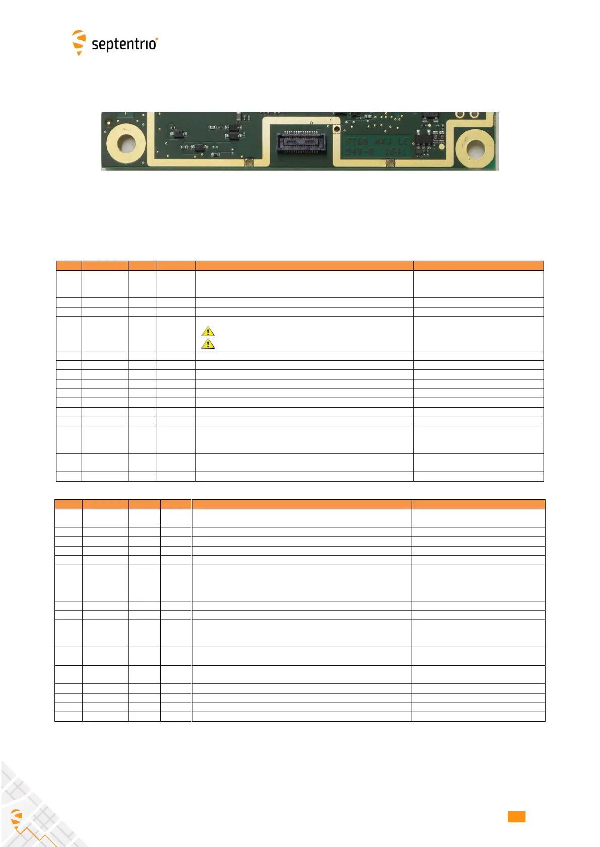
2.5.1 30-pin Connector
Connector type: Hirose 30 pins DF40HC (3.5)-30DS-0.4V(51)
Mating connector: Hirose DF40C-30DP-0.4V(51)
See the pin numbering convention in the above picture.
Both Vin pins (pin#1 and pin#2) must
be tied together.
USB data signal positive D+.
USB VBUS.
This pin cannot be used to power the receiver!
Mandatory if USB is used.
Serial COM 1 transmit line (inactive state is high)
Serial COM 2 transmit line (inactive state is high)
Serial COM 3 transmit line (inactive state is high)
Event A or TimeSync input.
Input can be connected to a push button used to control SD card
logging. Low state is interpreted as “button pressed”.
Debouncing must be done externally
(no debouncing circuit on board).
See also section 2.10.
Internal logging status indicator.
Max output current: 10 mA; output impedance: 20 Ohms
Both Vin pins (pin#1 and pin#2) must be
tied together.
USB data signal negative D-.
Reset input, active negative. Receiver resets when driven low.
Serial COM 1 receive line (inactive state is high).
PPS output. Output impedance: 50 ohms. Output current: 24 mA.
Polarity and rate user selectable. During start up, this pin is pulled
low with a 100-kOhm resistor.
See Reference Guide for operating instructions. Pulse duration: 5ms.
Serial COM 2 receive line (inactive state is high).
Serial COM 3 receive line (inactive state is high).
Receiver is put in standby mode (low power mode) when driven low.
Normal operation resumes when the pin level is high.
General purpose LED.
Max output current: 10 mA; output impedance: 20 Ohms
 Loading...