AsteRx-m2 OEM
8
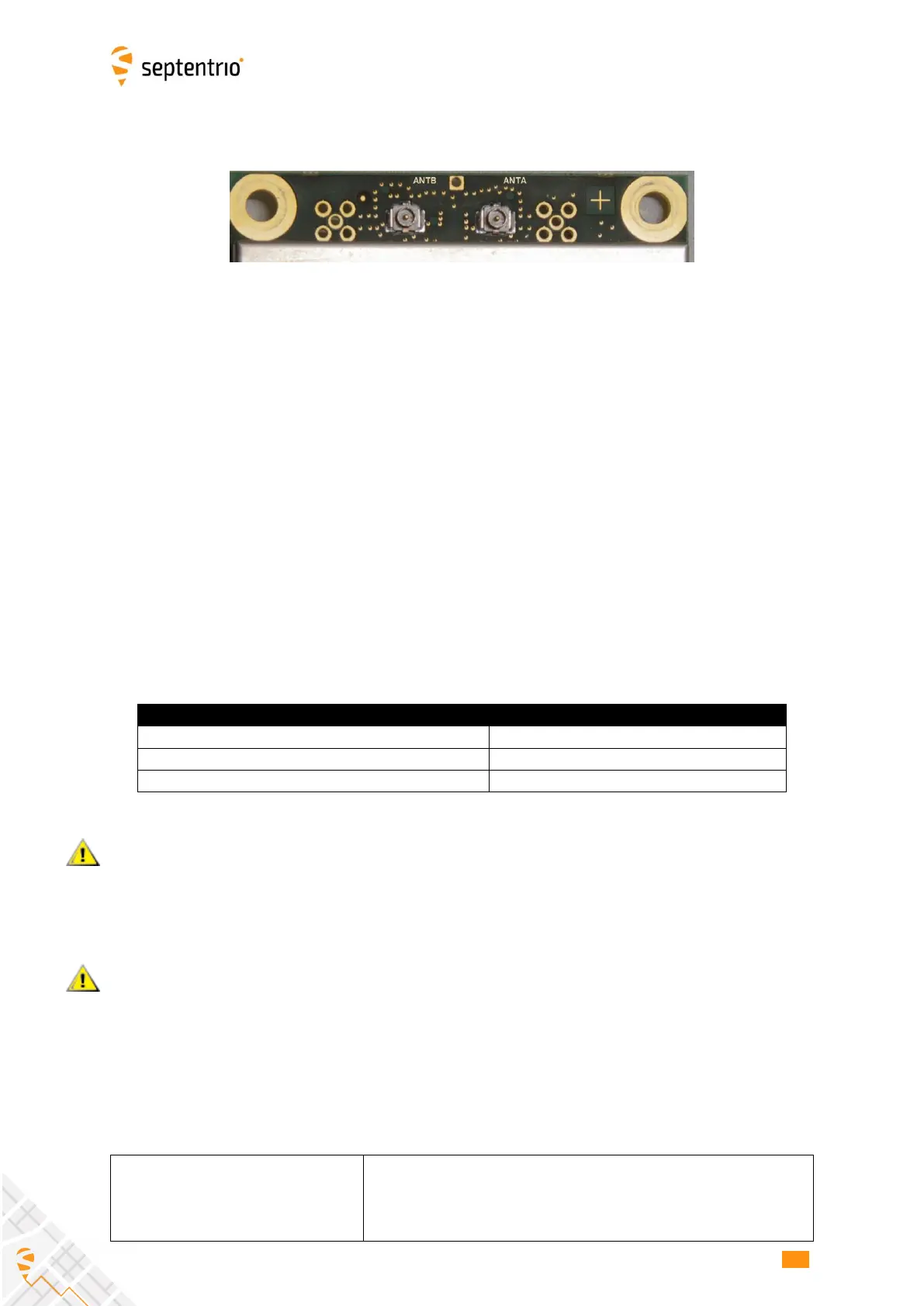
2.4 RF Interface
The receiver takes its RF signal from either the ANTA u.FL connector or the ANTB u.FL
connector. The signals from ANTA and ANTB are never combined, but the receiver selects
one of them as RF input and ignores the other. The ANTB connector is selected if an active
antenna is detected on that connector. Otherwise the ANTA connector is selected.
Typically, the ANTA connector is to be used for internal antennas that are always
connected to the AsteRx-m2, e.g. when the receiver and the antenna are integrated in the
same system. The ANTB connector is to be used for external antennas that, if connected,
replace the internal antenna.
Detection of the presence of an antenna on the ANTB connector is done by sensing the
current drawn by that connector. If the current exceeds 6mA, an active antenna is
assumed to be connected.
This default operation can be overruled with the setAntennaConnector command. Note
that, in the command line interface, the ANTA u.FL connector is referred to as “Int” (for
internal antenna), and the ANTB connector is referred to as “Ext” (for external antenna).
The table below summarizes the different configurations:
If the antenna is not powered by the receiver or when using passive antennas, automatic
detection will fail. For example, when the antenna is connected to the ANTB u.FL
connector through a power splitter with DC blocking, you must enter the
setAntennaConnector, Ext command to guarantee correct operation.
Likewise, when connecting the ANTB u.FL connector to a GNSS signal simulator, you must
enter the command “setAntennaConnector, Ext” to make sure the receiver is using the
ANTB antenna connector.
2.4.1 Electrical Specifications
3-5.5V DC, set via pin#18 of the 30-pin connector
• ANTA u.FL connector: DC applied only if the RF signal
is taken from that connector (see above)
• ANTB u.FL connector: DC always applied