EMC Considerations
27
Appendix B EMC Considerations
In applications in which the electronics are collocated with the GNSS antenna, cross-talk
could be a major concern. GNSS signals are very weak and easily interfered by radiated
harmonics of digital signals.
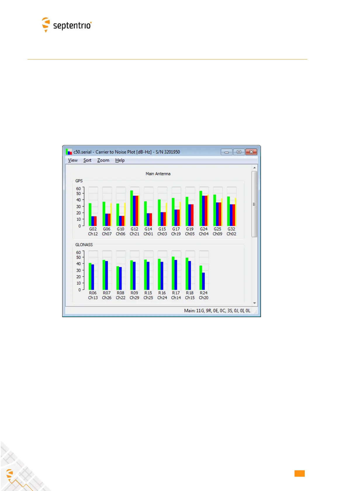
The most useful indicator of the signal reception quality is the C/N0 of the satellites in
view. The C/N0 can be viewed in the RxControl graphical interface by clicking View / Carrier
to Noise Plot. In open-sky conditions, the C/N0 values should reach up to 50 dB-Hz for the
strong signals on L1 and L5, and up to 45 dB-Hz on L2, as illustrated below.
If the maximum C/N0 is lower than expected, interference and cross-talk from nearby
electronics is likely, and the source of the problem needs to be identified. This is where
the RF spectrum monitor built in the AsteRx-m2 comes in handy. The spectrum monitor
can be accessed in RxControl under the View / Spectrum View menu. The spectrum can
also be monitored offline if the BBSamples SBF blocks are logged.
The figure below shows a clean open-sky L1-band spectrum. The bump at 1575MHz
corresponds to the GNSS signals at the L1/E1 frequency, and is normal.
 Loading...