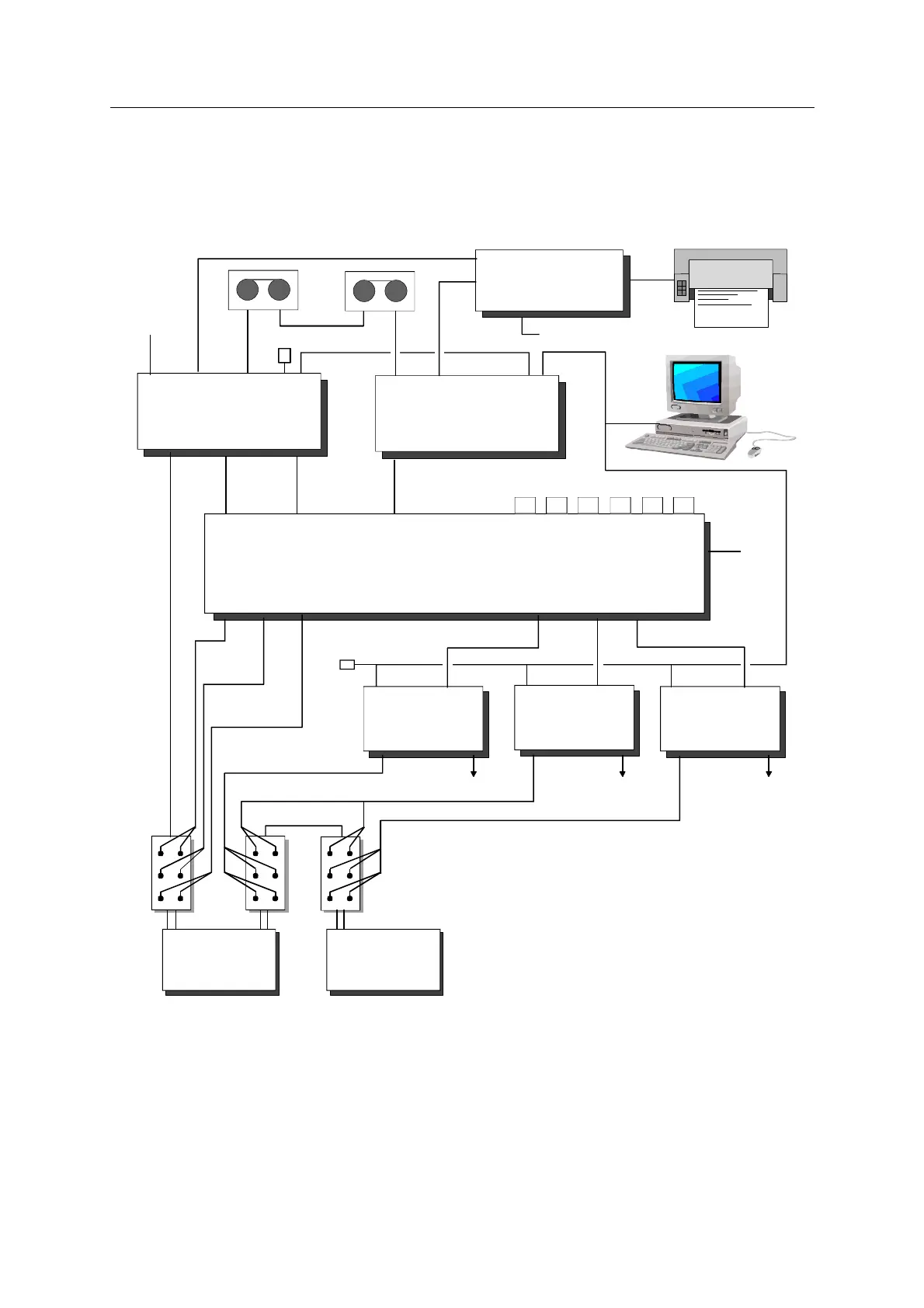
CONNECTING A DPG
Configurations with up to 8 APMs and up to 4 DPGs
0311385 Issue : April 1999
2-6
Configurations with up to 8 APMs and up to 4 DPGs
READ
CAMERA LAN
APM1
(master)
M / SAUX
CAMERA
SCSI
APM2
(slave)
M / S
AUX
MMCI4
IN
IN
IN
OUT
SU6
ACCB
ACCB
POWER
(110/220 V)
SQC-Pro
POWER (+12 V)
CAMERA
DPG1
RECORDER
ANALOG
Pilots
RADIO
LAN
DPG2
RECORDER
ANALOG
Pilots
RADIO
LAN
DPG3
RECORDER
ANALOG
Pilots
RADIO
LAN
(6)
M/S8
(6)
M/S7
(6)
M/S6
(6)
M/S5
(6)
M/S4
(1)
(6)
M/S3
BLASTER
M/S2
MMI-8
M/S1
BLASTER
BLASTER
(1)(3)
LAN
SCSI
HCI
50
Ω
AUX1 AUX2 AUX3 DPG1 DPG2 DPG3 DPG4
(4)
(4)
(4)
50
Ω
ACCB
(2) (2) (2)
SU6
to RADIO 1 to RADIO 2 to RADIO 3
Part No.
(1)
M/S cable 1A13071930B
(2)
MMI-8 ACCB cable 1A13077600A
(3)
APM BLASTER MMI-8 cable 1A13077599A
(4)
DPG RECORDER MMI-8 cable 1A13077598A
(5)
ANALOG PILOTS cable see VE432 DPG kit
(6)
14-19 plugs, M/S terminator 1A13072560
(with A wired to S, J wired to K)
(1), (2), (3), (4), and (6) contained in
Slip-Sweep option 1717077328B
(5) (5) (5)
This configuration should be used to connect either 4 or more APMs and 1 DPG, or
up to 8 APMs and up to 4 DPGs (Slip-sweep configuration).
Two pilots for each DPG are connected to the AUX line via ACCB interfaces. More
ACCB boxes can be used if more auxiliary channels need to be recorded.