CONNECTING A DPG
OUTPUT SIGNAL SPECIFICATIONS
0311385 Issue : April 1999
2-14
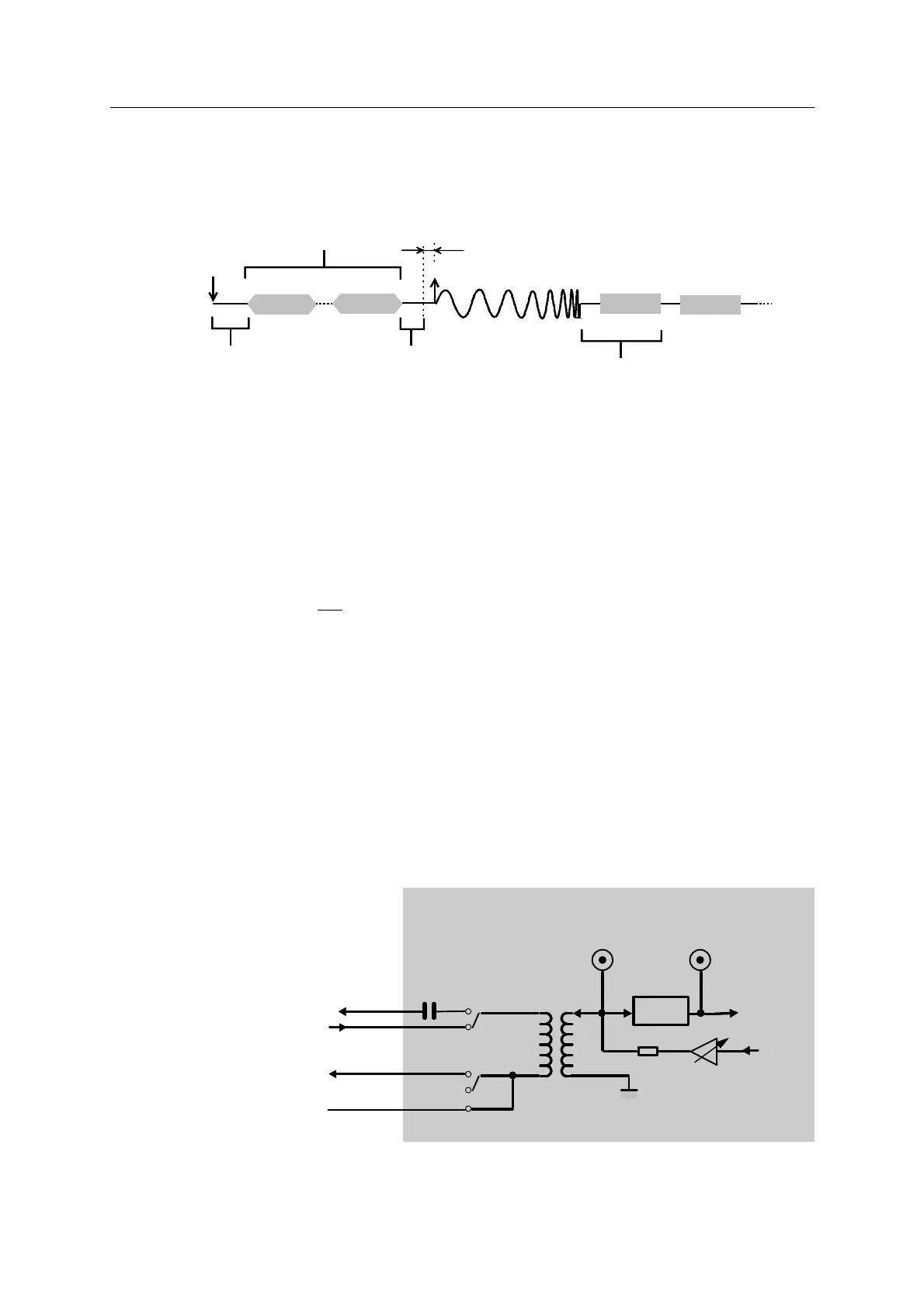
• • Sweep Start timing diagram
N × 390 ms
T
DSD 1
DSD 2
status
Sweep
40 ms
200 ms
TB
F. O.
Radio delay
F. O. = Start order from recording system
N = number of T0 DATA frames (T0 Repeat Times parameter) specified in
the T0 Time Setup on the HCI
T = approx. 580 ms for normal status.
4Add about 270 ms for GPS information if any.
4Add about 97 ∆t milliseconds for Time Extended QC information if enabled (i. e.
about 1 second for a 10-second sweep)
4Add about
27
5
∆
∆
f
t+
ms for Frequency Extended QC information if enabled
(i. e. about 0.7 s for an 80 Hz bandwidth 10 s sweep).
where ∆t is the sweep length (seconds)
∆f is the spectrum width (e. g. for a 20 to 80 Hz signal ∆f =80-20 = 60
Hz).
NOTE: Time Test conditions:
- MOTOROLA GM300 radio units
- MODEM transmission rate: 1200 bits/s.
• • VE432 RADIO INTERFACE
AGC
C169
C291
2.2
µ
F
DSD/
DPG
RADIO IN
The output should be terminated
into 600
Ω
. Add a resistor in
series or parallel connection on
the radio output (RADIO XMT
line) if required.
Digital potentiometer
AGC OUT
TP9
TP6
TP8
TP5
560
Ω
RADIO COM
RADIO PTT
RADIO RCV
RADIO XMT