Operating Instructions – Explosion-Proof AC Motors DR63/eDR63, DVE250/280
11
3
Basic structure of the motors
Motor Structure
3 Motor Structure
3.1 Basic structure of the motors
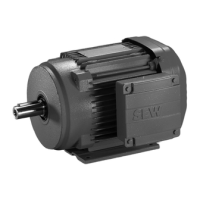
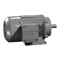
The following figure illustrates the structure of a DR63/eDR.63 motor:
INFORMATION
The following figures are block diagrams. They help you assign components to the
spare parts list. Deviations are possible depending on the motor size and version.
[1] Rotor [32] Retaining ring [113] Pan head screw [143] Adapter plate
[2] Retaining ring [35] Fan guard [114] Serrated lock washer [144] Screw
[3] Key [36] Fan [115] Terminal [216] Hex nut
[7] Flanged endshield [41] Shim [116] Terminal clip [230] Hex nut
[9] Screw plug [42] B-side endshield [117] Hex head screw [572] Gasket
[10] Retaining ring [44] Grooved ball bearing [118] Lock washer [823] Lock washer
[11] Grooved ball bearing [100] Hex nut [123] Hex head screw [829] Screw
[12] Retaining ring [101] Lock washer [126] Terminal clip
[13] Cap screw [103] Stud [129] Screw plug
[16] Stator [104] Supporting ring [131] Gasket for cover
[19] Screw [106] Oil seal [132] Terminal box cover
[22] Hex head screw [107] Oil flinger [134] Screw plug
[30] Oil seal [108] Nameplate [139] Hex head screw
[31] Key [109] Grooved pin [140] Lock washer
113
114
116
117
118
3510 9
143 36115
144
30
32
2
13
7
11 12
131
132
16
41
123
572
829
42
44
13
101
100
104
103
31
22
19
108
109
106
107
4
3
2
1
TF
TF
823
126
140
139
230
216
129
134
 Loading...
