Do you have a question about the SEW-Eurodrive DH 41B Series and is the answer not in the manual?
| Series | DH 41B |
|---|---|
| Protection class | IP20 |
| Cooling method | Forced air cooling |
| Overload capacity | 150% for 60 seconds |
| Control type | vector control |
| Communication interfaces | PROFIBUS DP, CANopen |
| Braking chopper | Integrated |
| Rated voltage | 380 to 500 V AC |
Details on the purpose and intended audience of the manual.
Explanation of signal words and section-related safety note structures.
Information essential for fault-free operation and warranty claims.
Describes the scope and relevance of safety information in the manual.
Specifies SEW-EURODRIVE's liability limitations for non-observance of instructions.
Lists related manuals and documentation for connected devices and functional safety.
Lists trademarks and registered trademarks used in the documentation.
States copyright information and restrictions on unauthorized use.
General safety notes to prevent injury and damage to property.
Instructions on safe use of the product and importance of reading documentation.
Defines qualifications for personnel performing mechanical and electrical work.
Specifies intended installation in electrical plants/machines and relevant directives.
Notes that the product cannot perform safety functions without a higher-level system.
Discusses risks associated with bus systems and the need for IT security.
Outlines the topics covered in the manual, including installation and interfaces.
Lists supplementary manuals required for configuration and startup.
Describes the MOVI-PLC® and CCU controllers, including performance classes.
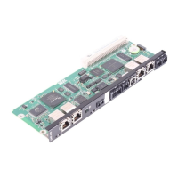
Details the types of DH.21B/41B controllers available and their form factors.
Tabulates device designs and their corresponding fieldbus interfaces.
Explains system bus and other communication interfaces of the controller.
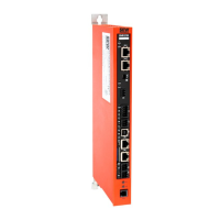
Information on installing the controller in a stand-alone housing.
Instructions for installing the option card in MOVIDRIVE® MDX61B.
Notes on installation or removal of the option card in MOVIAXIS® MXM.
Illustrates terminal positions for various controller configurations.
Detailed assignment and DIP switch settings for interfaces and functions.
Overview of the engineering software, its tasks, channels, and functions.
Guide to starting the software, creating projects, and establishing communication.
Procedure for connecting the unit to a PC using a USB connection.
Steps for connecting and configuring communication via Ethernet.
Detailed information on setting up the fieldbus and Ethernet switch.
Details on controller LEDs, their functions, and status indicators.
Information on controller LEDs for PROFIBUS and DeviceNet modes.
Details on controller LEDs for PROFINET and EtherNet/IP/Modbus/TCP modes.
Troubleshooting guide for communication issues on CAN system buses.
Instructions for proper disposal of electronic components and materials.
Lists general technical specifications like temperature, protection, and immunity.
Provides detailed technical specifications for the DH.21B/41B option card.
Provides detailed technical specifications for the DHF21B/41B option card.
Provides detailed technical specifications for the DHR21B/41B option card.
Specifies technical data for devices in stand-alone housing.
Details the ports used for PROFINET, EtherNet/IP, Modbus/TCP, and engineering.
Provides dimensional drawings for option cards in various housings.
