8
Operation
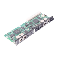
DH.21B/41B Controller
Manual – DHE/DHF/DHR21B (standard) and DHE/DHF/DHR41B (advanced)
63
8 Operation
8.1 DH.21B/41B Controller
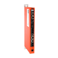
The DH.21B/41B controller comes equipped with 10LEDs (L1–L10) that indicate the
present state of the controller and the interfaces.
No. Name Function
LED1 CAN1 status CAN 1 system bus status
LED2 CAN2 status CAN2 system bus status
LED3 IEC program status IEC program status
LED4 Controller status Controller firmware status
LED5 User LED Freely programmable
LED6 DIO6/7 Status input or output DIO6/7
LED7 DIO4/5 Status input or output DIO4/5
LED8 DIO2/3 Status input or output DIO2/3
LED9 DIO0/1 Status input or output DIO0/1
LED10 24V / I/O OK Status of I/O voltage supply
8.1.1 LED "H1/H2" in stand-alone operation
LED "H1/H2" is reserved for stand-alone operation and the installation in
MOVITRAC
®
B.
8.1.2 LED "L1" (CAN 1 status)
LED "L1" indicates the status of the CAN1 system bus.
Status LED Possible cause Measure
Orange The CAN 1 system bus is being initial-
ized.
–
Green The CAN 1 system bus is being initial-
ized.
–
Flashing green with
0.5Hz
The CAN 1 system bus is in SCOM
suspend mode.
–
Flashing green with 1Hz The CAN 1 system bus is in SCOM On
mode.
–
Red The CAN 1 system bus is off (BUS-
OFF).
• Check and correct the cabling of
the CAN1 system bus.
• Check and correct the baud rate
set for the CAN1 system bus.
• Check and correct the terminating
resistors of the CAN1 system bus.
Flashing red with 1Hz Warning on the CAN 1 system bus.
• Check and correct the cabling of
the CAN1 system bus.
• Check and correct the baud rate
set for the CAN1 system bus.
22900055/EN – 08/2016
 Loading...
