8
Operation
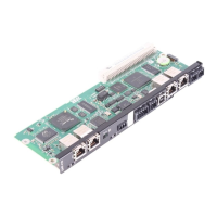
DHF21B/41B controller
Manual – DHE/DHF/DHR21B (standard) and DHE/DHF/DHR41B (advanced)
65
8.1.7 LEDs "L6", "L7", "L8", "L9" (DIOn/m)
LEDs "L6", "L7", "L8", "L9" indicate the status of the digital inputs and outputs (X31:3–
X31:10) n or m (e.g. DIO2/3).
X31
1
3
5
7
9
2
4
6
8
10
L6
L7
L8
L9
m n
2102564619
State LED Possible cause Measure
Off No voltage present.
–
Green Voltage at terminal n.
Red Voltage at terminal m.
Orange Voltage at terminals n and m.
8.1.8 LED "L10" (24V/ I/OOK)
LED "L10" indicates the status of the voltage supply for digital inputs and outputs.
Status LED Possible cause Measure
Green Voltage supply for the digital inputs or
outputs is OK.
–
Off Voltage supply is not applied at the di-
gital inputs or outputs.
1. Switch off the drive inverter in
which the controller is installed.
2. Check and correct the cabling of
the digital inputs/outputs according
to the electrical wiring diagram.
3. Check current consumption of the
connected actuators.
4. Switch on the drive inverter in
which the controller is installed.
Orange Voltage supply is applied at the digital
inputs or outputs. However, one of the
following faults has occurred:
• Overload on one or more digital in-
puts or outputs
• Overtemperature of the output
driver
• Short circuit in at least one of the
digital inputs or outputs
8.2 DHF21B/41B controller
The DHF21B/41B controller comes equipped with 8LEDs (L11–L18) that indicate the
present state of the PROFIBUS communication and electronics as well as the fieldbus
and DeviceNet
TM
interface.
No. Name Function
LED11 – Reserved
LED12 – Reserved
22900055/EN – 08/2016
 Loading...
