6
Electrical installation
Terminal positions
Manual – DHE/DHF/DHR21B (standard) and DHE/DHF/DHR41B (advanced)
21
6.1.2 DH.21B/41B controller in the stand-alone housing
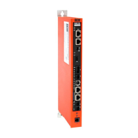
The following figure shows the position of the terminals at the front and the CAN wiring
via the X26 connector at the bottom side of the DHE21B/41B controller in the UO-
H11B stand-alone housing.
1
2 3 4 5 6
7
SEW drive
DC +24 V
GND
H1
H2
SC11 System bus +, CAN high
SC12 System bus -, CAN low
GND, CAN GND
120Ω
X35
X36
X37
2
4
6
1
3
5
X34
DHE41B
1
2
3
1
3
4
2
1
2
3
1
2
3
1
2
3
X32X33
2
4
6
1
3
5
8
10
7
9
X31
T1
S1
L1 L2 L3 L5XM L6 L7 L8 L9L4 L10
X26
X24
[2]
[1]
[3]
9007201363243019
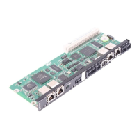
[1] DHE41B, see chapter "Terminal assignment and DIP switches"(→227)
[2] X24: COM1 (RS485) engineering interface
[3] X26: CAN1 system bus interface and voltage supply
For detailed information on terminal assignment, refer to chapter "Terminal
assignment and DIP switches"(→227).
22900055/EN – 08/2016
 Loading...
