Do you have a question about the SEW-Eurodrive MOVITRAC B MC07B0003-2B1-4-00 and is the answer not in the manual?
| Model | MC07B0003-2B1-4-00 |
|---|---|
| Type | MOVITRAC B |
| Product Type | Inverter |
| Rated Power | 0.37 kW |
| Rated Output Current | 2.3 A |
| Protection Class | IP20 |
| Mounting | Wall mounting |
| Input Voltage | 200 ... 240 V AC |
| Control Type | V/f control |
| Communication Interface | Modbus RTU, CANopen |
| Ambient Temperature | -10 to +50 °C |
| Storage Temperature | -25°C to +70°C |
| Relative Humidity | 5% to 95%, non-condensing |
Describes the three available variants: standard, technology, and coated PCB.
Provides a graphical overview of the MOVITRAC® B system components and connections.
Summarizes MOVITRAC® B types, motor power, current, and sizes in a table.
Details the key features and properties of MOVITRAC® B frequency inverters, including voltage range and overload capacity.
Introduces MOVITOOLS® MotionStudio software and its functions for MOVITRAC® B setup and diagnostics.
Covers compliance with CE, UL, CSA, GOST-R, and C-Tick standards for the inverters.
Provides general technical specifications applicable to all MOVITRAC® B sizes and powers, including environmental data.
Details the terminal assignments and electronic data for MOVITRAC® B, including inputs and outputs.
Specifies safety input terminal X17 data and safety-oriented 24V voltage supply requirements.
Presents detailed technical data, including dimensions and power ratings for various unit sizes.
Describes pluggable modules for enhancing MOVITRAC® B functionality, including keypads and communication options.
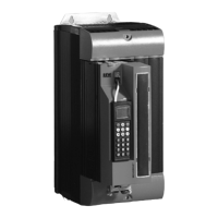
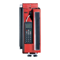
Introduces the DBG60B keypad for diagnostics, parameter setting, and startup operations.
Describes housing options for mounting the DBG60B keypad in control cabinets for protection.
Explains the UBP11A module for saving and transferring parameter data between the inverter and module.
Details the MBG11A module for remote speed control and multi-unit operation via speed control.
Covers the UWS11A adapter for converting RS232 to RS485 signals for PC communication.
Explains the UWS21B adapter for RS232 to RS485 conversion and PC connectivity.
Describes the USB11A adapter for connecting a PC/laptop to MOVITRAC® B via USB interface.
Provides information on BW braking resistors, including general data, PTC types, and flat design options.
Describes the BS touch guard accessory for braking resistors in flat design and its installation.
Shows dimension drawings and mounting methods for FKB10B braking resistor holders.
Explains the use of FKB11/12/13B kits for submounting braking resistors under the inverter.
Details the FHS support rail mounting kits for inverters and submounting braking resistors.
Information on ND line chokes, their purpose, types, and suitability for MOVITRAC® B.
Covers NF line filters for suppressing interference emission and their compatibility with MOVITRAC® B.
Describes ULF11A folding ferrites used for reducing interference on mains cables.
Explains HD output chokes for reducing radiated interference from motor cables.
Details EMC modules for achieving EMC limit class C1(B) on input/output sides.
Provides information on HF output filters for smoothing inverter output voltage and their selection criteria.
Covers fieldbus gateways for connecting to automation systems via SEW SBus, detailing various protocols.
Introduces the MOVI-PLC® controller, its unit types, and general description.
Explains SEW-EURODRIVE's control technology, including MOVI-PLC® and CCU options.
Provides technical data and dimension drawing for the UWU52A power supply.
Explains how to set and understand MOVITRAC® B parameters using keypad, PC software, or copying.
Details parameters for displaying process values like speed, frequency, current, and voltage.
Explains parameters related to inverter status, errors, and operating states.
Covers parameters for configuring analog inputs AI1 and AI2 for setpoint specification.
Details parameters for configuring binary inputs DI00 to DI05 for control functions.
Explains parameters for additional binary inputs DI10 to DI16.
Details parameters for configuring binary outputs DO01 to DO03 for signaling.
Parameters for displaying unit type, front module, and firmware information.
Explains parameters related to the error memory and fault logging for diagnostics.
Covers parameters for setpoint sources, speed ramps, and frequency scaling.
Detailed parameters for configuring the PI controller, including P-gain, I-component, and activation.
Parameters for adjusting the inverter to the motor, including limits, automatic adjustment, and protection.
Parameters for motor protection, including overload monitoring and cooling type settings.
Parameters for setting speed reference value, hysteresis, and deceleration time based on input signals.
Parameters for setting current reference value, hysteresis, and deceleration time based on output current.
Parameters for PI controller reference signal and actual value monitoring against limits.
Parameters for speed monitoring, deceleration time, and gear unit/motor monitoring.
Details the assignment of binary inputs and outputs for various control functions and responses.
Parameters for configuring basic unit binary outputs for signaling functions like fault or brake release.
Parameters for configuring the optional analog output AO1 for various output signals.
Parameters defining fundamental control properties, including operating modes, DC braking, and flying start.
Parameters for setting standstill current to maintain motor temperature or enable auto-start.
Parameters for enabling automatic inverter operation based on the main setpoint and enabling the drive.
Parameters for controlling the motor brake, including release and application times, and response to inhibit.
Parameters for the speed skip function to suppress motor speed within a window, reducing vibration.
Parameters for implementing automatic functions like speed synchronization and communication via RS485 or SBus.
Parameters for enabling or disabling manual operation control keys (RUN/STOP).
Parameters for activating the energy-saving function to reduce power consumption during part-load operation.
Parameters related to unit functions, including quick menu, language selection, factory reset, and parameter lock.
Parameters for configuring RS485 and SBus serial communication settings, including addresses and timeouts.
Parameters for enabling or disabling 4-quadrant operation, which requires a braking resistor.
Parameters for programming fault responses to external faults, system bus timeouts, and unit malfunctions.
Parameters controlling manual and automatic reset behavior after an error occurs.
Parameters for scaling the actual speed value for user-specific display on the FBG keypad.
Parameters for setting the nominal cycle frequency at the inverter output.
Parameters for defining the content of process output data words (PO1-PO3) and input data words (PI1-PI3).
Outlines the step-by-step process for project planning, from clarification to component compilation.
Lists available options and conditions for simple applications like vertical and horizontal movements.
Describes application-specific planning considerations for trolleys and hoists, including thermal and safety aspects.
Illustrates the speed-torque characteristic curve and explains load limits and motor heating.
Provides guidance on selecting motors, including basic recommendations, voltage-frequency curves, and dynamic applications.
Explains how MOVITRAC® B inverters calculate load and permitted continuous current based on various factors.
Discusses the thermal model's dynamic limiting of output current at low frequencies and recommended average output current.
Covers approval requirements for SEW-EURODRIVE explosion-proof motors used with MOVITRAC® B.
Guides on selecting braking resistors, including safety warnings, connection types, and peak power calculation.
Details the SEW brake system, brake rectifier function, activation, and parameters.
Covers permitted voltage supply systems, line contactors, fuses, cable cross sections, and motor cable length.
Covers operating modes, motor currents, cable length, motor size, and output filters for multi-motor systems.
Explains the optional use of line chokes for overvoltage protection, line current smoothing, and charging current limitation.
Addresses EMC compliance, interference immunity, emission, and EMC-compliant installation measures.
Provides instructions for using HF output filters, including important notes, installation, and VDC link connection.
Information on cable types, 0V cables, coupling relays, and external voltage supply.
Explains the use of internal and external DC 24 V supplies for basic units and options, with a sample calculation.
Describes how to operate two motors on one inverter using different parameter sets via binary input or fieldbus.
Explains the hierarchy of operating states and how control signals interact.
Details the PI controller structure, parameterization, setpoint selection, actual value detection, and inverter control.
Provides practical examples of applying MOVITRAC® B in systems like speed-controlled agitators, trolleys, and PI controller applications.
Explains the purpose and scope of the documentation for users.
Describes the grading and meaning of signal words used in safety notes.
Outlines requirements for warranty claims, emphasizing adherence to documentation.
States SEW-EURODRIVE's exclusion of liability for non-observance of documentation.
Provides copyright information for the documentation.
Lists product names and trademarks used in the publication.
Provides introductory safety notes predominantly for frequency inverters and motors.
Covers general safety information regarding operation, transportation, and handling of frequency inverters.
Defines qualified personnel for mechanical and electronic work on the product.
Specifies the intended use of frequency inverters and applicable standards (Low Voltage, EMC).
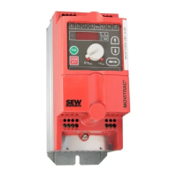
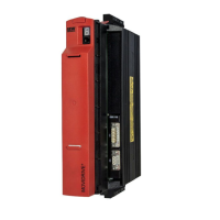
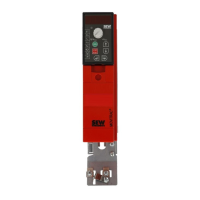
Details the unit structure and component identification for MOVITRAC® B sizes 0XS, 0S, and 0L.
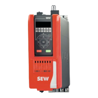
Shows the unit structure and component identification for MOVITRAC® B sizes 1, 2S, and 2.
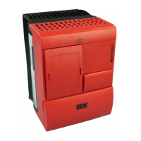
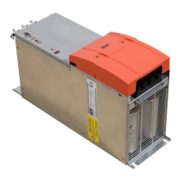
Illustrates the unit structure and component identification for MOVITRAC® B size 3.
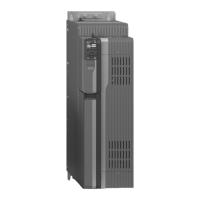
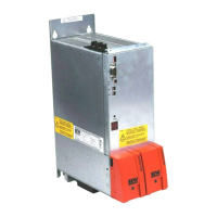
Depicts the unit structure and component identification for MOVITRAC® B sizes 4 and 5.
Explains the structure and meaning of the MOVITRAC® B type designation.
Describes the information presented on the MOVITRAC® B nameplate.
Lists recommended tools, such as a specific screwdriver, for connecting electronics terminals.
Provides essential notes for installing MOVITRAC® B units, including clearance, mounting, cable routing, and EMC compliance.
Guides on installing optional components like ND line chokes, NF line filters, and HF output filters.
Provides key points for UL-compliant installation, including cable types, terminal torques, and voltage supply systems.
Details the scope of delivery for loose items, including shield plates, connectors, and touch guards.
Specifies requirements for installing a cold plate for size 0 units, focusing on thermal connection.
Provides instructions for electricians to deactivate EMC capacitors for size 0 units, noting the loss of EMC filter function.
Presents a comprehensive wiring diagram for connecting the MOVITRAC® B inverter with various options.
Explains how to connect TF thermistors or TH bimetallic switches for winding temperature monitoring.
Details the connection of BW braking resistors and notes on overload protection and terminal settings.
Covers overload protection for BW braking resistors and brake rectifier connection requirements.
Guides on installing various front modules (analog, digital, communication) to enhance basic unit functionality.
Instructions for installing the MBG11A speed control module, including mounting options and connection.
Covers essential requirements and safety precautions for successful drive startup.
Lists preliminary tasks and tools required for startup, emphasizing safety precautions.
Explains how to enable the motor via terminals after exiting manual operation, covering analog setpoints.
Covers startup procedures for explosion-proof motors, including approval requirements and software usage.
Provides a brief procedure for startup with factory settings, including direct motor connection.
Explains keypad layout, functions, and operation for navigating menus and controlling the drive.
Guides on startup using the DBG60B keypad, including required data and language selection.
Guides on performing startup using PC software, including connecting the unit and using online help.
Explains how to specify external setpoints via terminals, serial interface, or speed control module.
Explains how to back up parameter data using FBG11B keypad, DBG60B keypad, or UBP11A module.
Lists and explains return codes encountered when entering or editing parameters in the FBG11B keypad.
Describes the status displays on the basic unit and FBG11B keypad, including LED codes and unit status.
Covers basic displays, information messages, and keypad functions for the DBG60B keypad.
Provides information on the unit's error memory and switch-off responses to faults.
Lists and describes various error codes (F00-F113), their possible causes, and recommended measures.
Provides contact information for SEW-EURODRIVE service, including hotline and repair procedures.
Provides recommendations for units stored for extended periods, including regeneration procedures.