System Manual – MOVITRAC® B
233
8
Installing FIO11B/21B, FSC11B/12B and FSE24B
Installation
8.12 Installing FIO11B/21B, FSC11B/12B and FSE24B
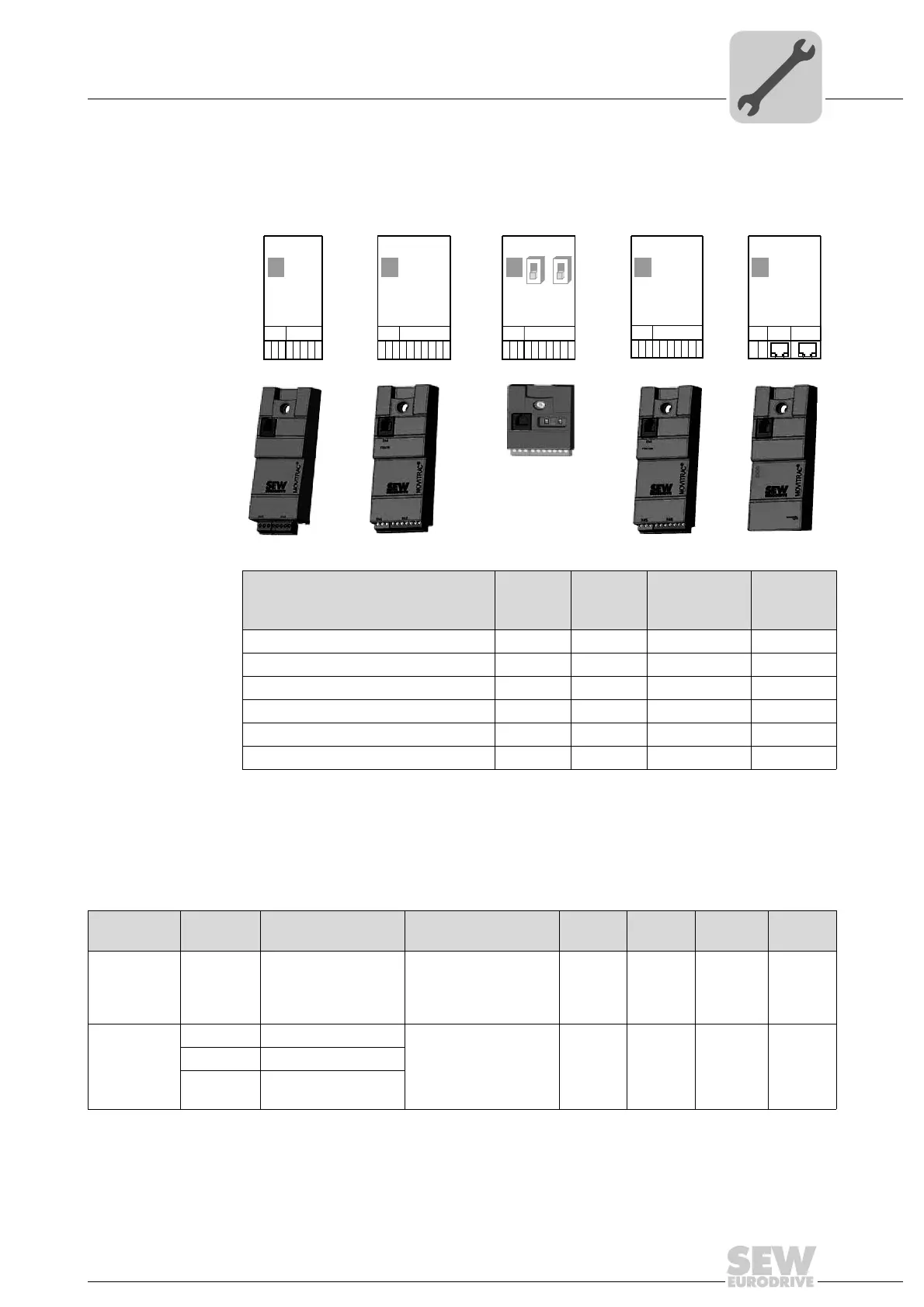
You can enhance the basic units with the FIO11B/21B, FSC11B/12B and FSE24B mod-
ules.
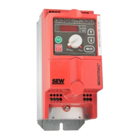
8.12.1 Connection and installation of the front modules
Always attach the option to the unit with the screw that is included in the delivery. For
size 0, mount the spacer bolt first. The bolt is already installed in sizes 1 and higher. Fit-
ting the screw secures the high-frequency EMC connection between the basic unit and
the option.
18014398749591179
Connection/module type FIO11B FIO21B FSC11B/12B FSE24B
Analog
module
Digital
module
Communica-
tion
Communi-
cation
Analog input/output X40 Yes No No No
Binary inputs X42 No Yes No No
RS485 for diagnostics (RJ10) X44 Yes Yes Yes Yes
RS485 terminal connection X45 Yes No Yes No
SBus terminal connection X46 No Yes Yes No
EtherCAT connection (2 × RJ45) X30 No No No Yes
X45
X46
1
23456HL⊥
FSC11B
7
X44
S1 S2
OFF
ON
X45
X40
1
2345HL⊥
FIO11B
X44
X46
X42
1
23456
FIO21B
7
X44
X44
X47
RUN
ERR
SYS-F
X30 IN
X30 OUT
FSE24B
EtherCAT
®
X47
1 2
FSE24B
X44
X30 IN
X30 OUT
X45
X46
1
23456HL⊥
FSC12B
7
X44
HL⊥
Function Terminal Description Data FIO11B FIO21B FSC11B/
12B
FSE24B
Service
interface
X44 Via RJ10 plug con-
nector
Only for service pur-
poses
Maximum cable length
3 m (10 ft)
Yes Yes Yes Yes
RS485 inter-
face
X45:H ST11: RS485+ Connected in parallel
with X44
Yes No Yes No
X45:L ST12: RS485–
X45:
⬜ GND: Reference
potential
Phone: 800.894.0412 - Fax: 888.723.4773 - Web: www.clrwtr.com - Email: info@clrwtr.com
 Loading...