System Manual – MOVITRAC® B
231
8
Brake rectifier connection
Installation
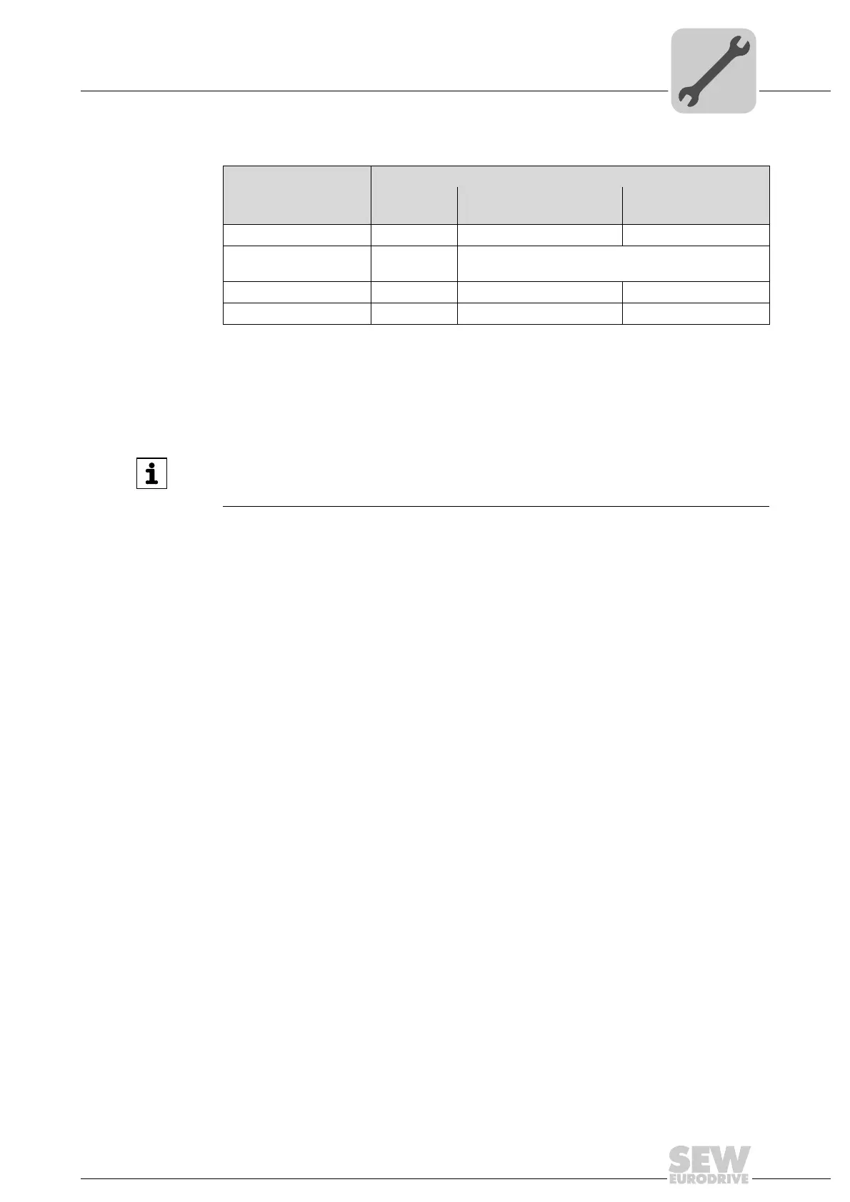
Overload protection for braking resistors BW:
8.11 Brake rectifier connection
Use only contactors of utilization category AC-3 for K11 and K12.
Switch off the brake on the DC and AC sides with:
• All hoist applications.
• Drives which require a rapid brake response time.
If the brake rectifier is installed in the control cabinet, route the connecting leads be-
tween the brake rectifier and the brake separately from other power cables. Routing to-
gether with other cables is only permitted if the other cables are shielded.
Overload protection
Braking resistor type Design
specified
Internal temperature
switch (..T / ..P)
External bimetallic
relay (F16)
BW.. – – Required
BW..-T
1)
/ BW..-P
1) Permitted installation: On horizontal or vertical surfaces with brackets at the bottom and perforated sheets
at top and bottom. Improper installation: On vertical surfaces with brackets at the top, right or left.
– One of the two options (internal temperature switch/
external bimetallic relay) is required.
BW..-003 / BW..-005 Adequate – Permitted
BW1 – BW4 Adequate – –
INFORMATION
The connection of the brake rectifier requires a separate supply system cable; supply
from the motor voltage is not permitted!
Phone: 800.894.0412 - Fax: 888.723.4773 - Web: www.clrwtr.com - Email: info@clrwtr.com
 Loading...