33
27DV-S100
27DV-CS10
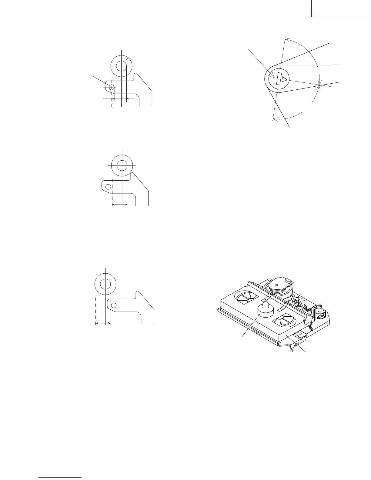
Figure 1-15.
2. Visually check to see if the right edge of the tension
pole is within the 2.3 ± 0.25 from the right edge of the
Sup guide shaft.
2.3 ± 0.25
Sup guide shaft
Tension pole
Make the adjustment with the beginning of a T-120 tape.
At left side from the center line
2.3 ± 0.25
Figure 1-16.
Insert the slotted screwdriver in the tension pole adjuster,
and rotate counterclockwise.
At right side from the center line
2.3 ± 0.25
Figure 1-17.
Insert the slotted screwdriver in the tension pole adjuster,
and rotate clockwise.
• Problems caused by maladjustments
1. Images onscreen may get distorted.
Tension pole adjuster adjusting range
90°
90°
Tension pole adjuster
Figure 1-18.
Adjust so that the delta mark of tension pole adjuster is
within 90° range (left, right).
CHECKING AND ADJUSTMENT OF
RECORD/PLAYBACK BACK TENSION
• Remove the cassette housing control assembly.
• After short-circuiting R7057 and JUMPER:420
provided on the main PWB, plug in the power cord,
then turn off the power.
• Setting
1. Turn off the power switch.
2. Open the torque cassette meter and fix with tape.
3. Set the cassette tape into the unit.
4. Put the weight (500g) on the cassette torque meter.
5. Turn on the power switch.
500g
Weight to prevent
float (500g)
Cassette torque
meter
Figure 1-19.
• Checking
1. Push the REC button to place the unit in the SP record
mode.
2. At this time ascertain that the back tension is within the
setting (36.5 to 52g·cm) by seeing the indication of
torque cassette meter.