36
27DV-S100
27DV-CS10
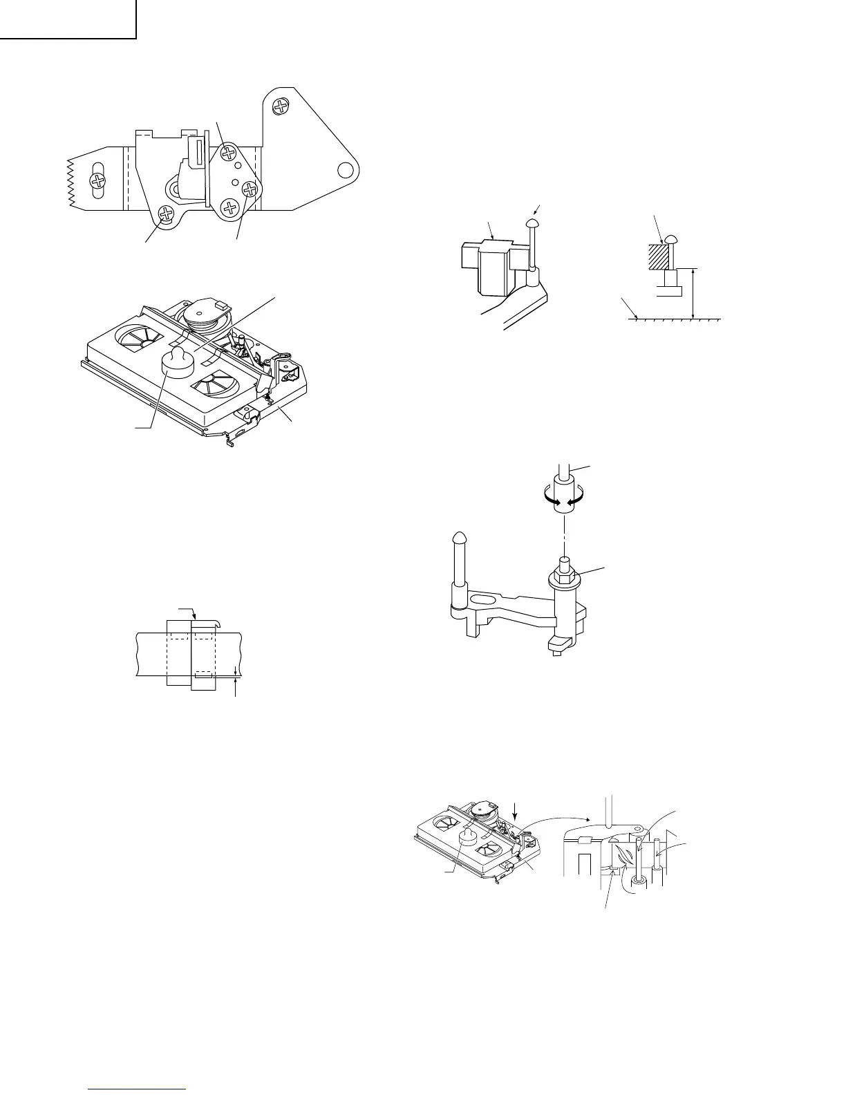
A/C HEAD HEIGHT ROUGH ADJUSTMENT
• Setting
1. Set the cassette tape in the unit.
2. Press the PLAY button to put the unit in the playback
mode.
3. Roughly adjust the height of the A/C head by turning
the height screw until the tape is in the position shown
below.
500g
Azimuth screw
Height screw
Tilt screw
Cassette tape
Mechanism chassis
Weight to prevent
float (500g)
Figure 1-26.
0.3mm
A/C head
Tape
• Adjustment
Adjust the height screw visually so that the control head is
visible 0.3mm below the bottom of the tape.
• Problems caused by maladjustments
1. Tapes may get scratched
2. Images onscreen distorted.
Figure 1-27.
HEIGHT ADJUSTMENT OF REVERSE
GUIDE
1. Adjust the height from the mechanism chassis to the
reverse guide lower flange to 13.38 mm, using the
reverse guide height adjustment jig, in tape loading
state. (Refer to Figure 1-28 (a) (b).)
Reverse guide height
adjusting jig
Reverse guide
Mechanism
chassis
Reverse guide height
adjusting jig
13.38mm
Figure 1-28.
(a) (b)
2. Rotate counterclockwise the reverse guide height ad-
justment nut 1/10 turn. (For height adjustment use the
reverse guide height adjustment box driver (JiGDRiVER
11055)).
Box driver
CCW
Height adjusting nut
Figure 1-29.
3. Set the tape, and check for tape crease near the
reverse guide in the playback mode.
If crease is found, turn the reverse guide adjustment
nut to remove crease. (As for crease check refer to
Figure 1-30.)
500g
Weight to
prevent float (500g)
A
Capstan
motor shaft
Fixing guide
An example of
crease near the
reverse guide
Reverse guide
Mechanism
chassis
* Check for crease from the A direction.
Figure 1-30.
• Problems caused by maladjustments
1. Tapes may get scratched.