Do you have a question about the Sharp AL-2040CS and is the answer not in the manual?
| Brand | Sharp |
|---|---|
| Model | AL-2040CS |
| Category | All in One Printer |
| Language | English |
Details the fundamental technical specifications of the copier.
Outlines the operational parameters and capabilities of the copier.
Describes the performance metrics and capabilities related to copying.
Information specific to the GDI printer functionality and requirements.
Details the functionality and specifications of the scanner unit.
Information regarding the Single Path Feeder functionality and its specifications.
Lists and describes the consumable parts for the copier.
Specifies the recommended environmental conditions for optimal operation.
Explains how to identify production control numbers (lot numbers) on parts.
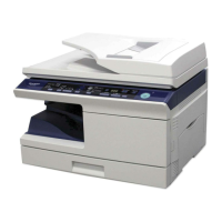
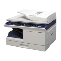
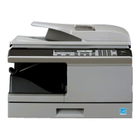
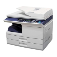
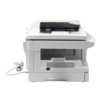
Shows the exterior view of the copier and its main external parts.
Identifies and labels the key internal components of the copier.
Explains the function of each key, indicator, and display on the operation panel.
Explains how to use the SCAN key to initiate scanning operations and select applications.
Lists and describes the motors and solenoids used in the copier's mechanisms.
Lists and describes the sensors and switches utilized in the copier's operation.
Identifies the various Printed Wiring Board (PWB) units within the copier.
Provides a detailed cross-sectional diagram of the copier's internal structure.
Step-by-step instructions for installing the copier in its operating location.
Important safety notes and precautions to follow when handling the copier.
Instructions for verifying that all components and accessories are included after unpacking.
Detailed steps for safely unpacking the copier unit from its packaging.
Instructions for removing protective packing materials from the copier.
Procedure for installing the TD cartridge into the copier.
Instructions on how to load paper correctly into the paper trays.
Steps for connecting power and turning the copier on and off.
Instructions for installing necessary software, including drivers and utilities.
Details for installing printer and MFP drivers for AL-2030 and AL-2040CS.
Instructions for installing scanner driver, Sharpdesk, and Button Manager.
Guides for connecting the copier to a computer using USB or LAN.
Step-by-step guide for connecting the machine via USB cable.
Instructions for connecting via LAN for network printing functionality.
Procedures and precautions for moving the copier unit.
Presents a functional diagram illustrating the copy process cycle.
Describes the general steps involved in the printing process.
Details the sequential steps involved in the printing process.
Provides detailed explanations of each stage in the actual print process.
Provides detailed explanations of each stage in the actual print process.
Explains optical discharge, Scorotron charging, process control, and developing bias.
Describes the basic configuration and operational flow of the copier.
Describes the sequence of operations for copying, from setting conditions to paper output.
Explains how the unit functions as a printer and a scanner.
Details the scanner unit, including optical and drive systems.
Details the scanner unit, including optical and drive systems.
Explains the light source, mirrors, lens, CCD, and resolution of the scanner.
Describes the components and mechanism of the scanner's drive system.
Details the basic structure, beam path, and composition of the laser unit.
Details the basic structure, beam path, and composition of the laser unit.
Provides a general description of the fuser section, including its components and thermal control.
Provides a general description of the fuser section, including its components and thermal control.
Explains the paper feeding and transport mechanisms.
Explains the step-by-step process of feeding paper from the cassette.
Describes the procedure for feeding paper manually using multiple feed options.
Explains the mechanism for detecting the installation of a new drum.
Provides an overview of the Single Path Feeder (SPF) section.
Details the document transport path and basic composition of the SPF.
Explains the operational aspects and conditions of the SPF.
Explains conditions that lead to paper jams in the SPF.
Details how book document detection is performed by the SPF.
Provides procedures for disassembling and assembling the high voltage section.
Instructions for cleaning the charger wire.
Steps for replacing the charger wire in the high voltage section.
Provides procedures for disassembling and assembling the operation panel.
Provides procedures for disassembling and assembling the optical section.
Provides procedures for disassembling and assembling the fusing section.
Provides procedures for disassembling and assembling the tray paper feed/transport section.
Provides procedures for disassembling and assembling the manual paper feed section.
Provides procedures for disassembling and assembling the rear frame section.
Provides procedures for disassembling and assembling the power section.
Provides procedures for disassembling and assembling the SPF unit and its components.
Steps for removing the rear cabinet to access the SPF.
Procedures for removing the SPF unit itself.
Steps for disassembling the SPF motor.
Steps for disassembling SPF pick-up and paper feed rollers.
Steps for disassembling the SPF paper exit roller.
Steps for disassembling SPF set sensor and scan front sensor.
Steps for disassembling the SPF transport roller.
Provides procedures for disassembling the 2nd cassette section.
Steps for removing the 2nd cassette paper feed unit.
Details disassembly for sensors, rollers, and solenoids in the 2nd cassette.
Steps for removing the paper sensor in the 2nd cassette.
Steps for removing the cassette detection switch.
Steps for removing the paper feed solenoid.
Steps for removing the transport roller.
Steps for removing the paper feed clutch.
Steps for removing the 2nd paper feed roller.
Procedures for adjusting copier magnification and image position.
Explains automatic and manual adjustment of copy magnification ratios.
Details the procedure for adjusting the magnification ratio in the main scanning direction.
Details the procedure for adjusting the magnification ratio in the sub scanning direction.
Details various image position adjustments using simulation modes.
Adjusts the copy image position and lead edge void quantity.
Adjusts the image rear edge void amount on the copy paper.
Adjusts copy image position and center offset when scanning a document.
Specifies when the copy density adjustment should be performed.
Important considerations before performing copy density adjustment.
Lists the necessary tools and test charts for copy density adjustment.
Describes the features utilized for copy density adjustment.
Step-by-step procedure for adjusting the copy density.
Procedures for adjusting high voltage components like the main charger.
Procedure for adjusting the main charger grid bias voltage.
Procedure for checking the DV bias voltage.
Procedures for adjusting duplex copy settings.
Adjusts the reverse position for duplex copying.
Adjusts the trailing edge void in duplex copy mode.
Automatically adjusts the SPF scan position for optimal scanning.
Adjusts the magnification ratio in the SPF sub scanning direction.
Corrects the black level for optimal white balance adjustment.
Details the key sequence required to enter the service simulation mode.
A comprehensive list of available simulation modes and their operations.
Detailed descriptions of various simulation modes and their functions.
Details simulations for mirror scanning, SPF aging, and sensor checks.
Covers simulations for high voltage, duplex motor, and toner motor operations.
Explains simulations for resetting troubles, checking counters, and clearing counts.
Details simulations for various system setups like SPF, duplex, and destination.
Explains simulations for copy lamp and paper/resist solenoids.
Covers simulations for warm-up, aging, developing bias, and charger operations.
Details simulations for duplex and toner motor operations.
Explains simulations for displaying and clearing various counters.
Covers simulations for main motor operation, polygon motor, and SPF setup.
Details simulations for setting up cassettes, duplex, and destination.
Covers simulations for machine conditions, void setup, and CE mark control.
Explains simulations for canceling drum life stops and checking memory capacity.
Allows setting the polygon motor OFF time after printing.
Covers simulations for transfer timing and side void adjustments.
Explains simulations for energy-save lamp and paper sensor status.
Details simulations for OC cover float detection level and margin settings.
Covers simulations for setting fusing temperature in various copy modes.
Procedure to set copy density for 300dpi resolution in different modes.
Procedure to set copy density for 600dpi resolution in different modes.
Procedure to set image contrast for 300dpi resolution.
Allows setting gamma table or AE operation modes, and PHOTO image process settings.
Adjusts exposure correction quantity in SPF mode via Vref voltage.
Procedure to set image contrast for 600dpi resolution.
Sets AE and AE (toner save) limit values.
Adjusts image clarity and shading-off in each mode.
Sets color reproduction for each mode, selecting easily or difficult-to-copy colors.
Adjusts magnification ratios for main scanning and SPF sub scanning.
Puts the machine into Flash ROM writing mode for program updates.
Adjusts copy image position and lead edge void quantity.
Adjusts SPF copy lead edge position.
Adjusts copy image position and center offset when scanning.
Adjusts reverse memory copy operations for duplex copying.
Adjusts the rear edge void quantity in duplex copy.
Adjusts contact pressure against resist rollers.
Automatically adjusts the SPF scan position for optimal scanning.
Performs a check of the polygon motor's HSYNC output.
Displays the detection level of the white board for shading.
Corrects the black level for optimal white balance adjustment.
Sets wait time before light quantity level stabilization.
Sets the band for light quantity stabilization.
Lists all error codes that may occur during operation.
Provides detailed explanations and remedies for various trouble codes.
Details trouble codes related to memory, LSU, and shading issues.
Explains trouble codes for copy lamp, thermistor, and heat roller.
Details trouble codes for feeding errors and motor lock detections.
Covers trouble codes related to EEPROM errors and counter checks.
Details trouble codes for white shading errors and abnormal laser output.
Explains trouble codes for copy lamp and thermistor issues.
Covers trouble codes for high and low heat roller temperatures.
Details trouble codes related to feeding issues and motor lock detections.
Explains trouble codes for scanner return and polygon motor lock issues.
Covers trouble codes for EEPROM read/write errors and counter check sums.
Explains how to set toner save mode and the two power save modes.
Details setting the auto clear time and copy resolution for AUTO/MANUAL modes.
Explains how to set and change various user program parameters.
Covers user programs for preventing OC copies and setting paper width.
Details user programs for copy start state and fusing temperature.
Presents a high-level block diagram of the copier's electrical system.
Shows the wiring connections for the AL-2030 MCU PWB.
Shows the wiring connections for the SPF unit.
Displays the wiring connections for the 2nd cassette unit.
Shows wiring for the NIC PWB (network interface).
Shows the wiring connections for the AL-2040CS MCU PWB.
Shows wiring for the SPF unit.
Displays wiring for the 2nd cassette unit.
Shows wiring for the NIC PWB.
A reference list of signals, their names, functions, and sections.
Schematic diagram of the MCU PWB's CPU section.
Schematic diagram of the MCU PWB's Graphic ASIC section.
Schematic diagram of the MCU PWB's memory section.
Schematic diagram of the MCU PWB's driver section 1.
Schematic diagram of the MCU PWB's driver section 2.
Schematic diagram of the MCU PWB's driver section 3.
Schematic diagram of the MCU PWB's noise filter and pull-up circuits.
Schematic diagram of the MCU PWB's connector section 1.
Schematic diagram of the MCU PWB's connector section 2.
Schematic diagram of the MCU PWB's scanner interface section.
Schematic diagram of the MCU PWB's USB2.0 interface section.
Schematic diagram of the MCU PWB's CRUM interface section.
Schematic diagram of the MCU PWB's network interface section.
Schematic diagram of the Operation Panel (OPE) PWB with 7-segment display.
Schematic diagram of the copier's power supply unit.
Provides notes on using lead-free solder thread and soldering techniques.
Important safety information regarding battery replacement.
Important safety information regarding battery disposal.