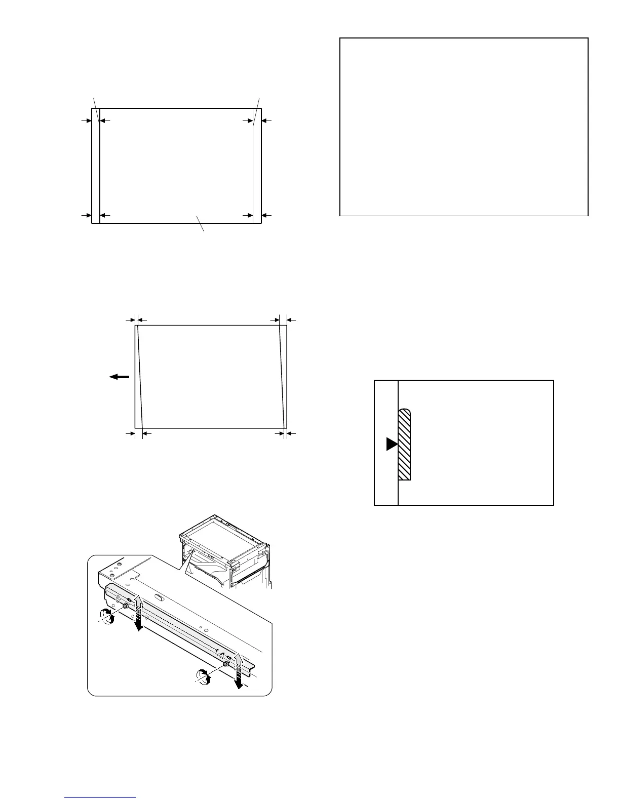
1) Making of a test sheet
Make test sheet by drawing parallel lines at 10mm from the both
ends of A3 (11" x 17") white paper as shown below. (These lines
must be correctly parallel to each other.)
2) Make a normal (100%) copy of the test sheet on A3 (11" x 17")
paper. (Fit the paper edge with the glass holding plate edge.)
3) Measure the distances (La, Lb, Lc, Ld) at the four corners as
shown below.
When La = Lb and Lc = Ld, no need to perform the procedures 4)
and 5).
4) Move the mirror base F rail position up and down (in the arrow
direction) to adjust.
(Note) If the rear side rail is used for the adjustment, the scanning
position of the white balance sheet is shifted and "E7-04" may
occur only when scanning with the SPF. Therefore it is ad-
visable to use the front side rail for the adjustment.
• When La > Lb
Shift the mirror base B rail upward by the half of the difference
of La – Lb.
• When La < Lb
Shift the mirror base B rail downward by the half of the
difference of Lb – La.
Example: When La = 12mm and Lb = 9mm, shift the mirror
base B rail upward by 1.5mm.
• When Lc > Ld
Shift the mirror base B rail downward by the half of the
difference of Lc – Ld.
• When Lc < Ld
Shift the mirror base B rail downward by the half of the
difference of Ld – Lc.
* When moving the mirror base rail, hold the mirror base rail with
your hand.
<Adjustment specification>
La = Lb, Lc = Ld
5) After completion of adjustment, manually turn the mirror base
drive pulley, scan the mirror base A and mirror base B fully, and
check that the mirror bases are not in contact with each other.
* If the mirror base rail is moved extremely, the mirror base may be
in contact with the frame or the original glass. Be careful to avoid
this.
(5) Main scanning direction (FR direction) magnification
ratio adjustment (SIM 48-1)
Note: Before performing this adjustment, be sure to check that the
CCD unit is properly installed.
1) Put a scale on the original table as shown below.
2) Execute SIM 48-1.
3) After warmup, shading is performed and the current set value of
the main scanning direction magnification ratio is displayed on the
display section in 2 digits.
4) Select the mode and press the start key again.
5) Auto correction mode (AE lamp ON)
The mirror unit moves to the shading position, and the reference
width of the reference white plate is scanned, and the correction
value is automatically calculated from that scanned value.
The correction value is displayed and a copy is made.
6) Compare the scale image and the actual scale.
If a fine adjustment is required, switch to the manual correction
mode with the magnification ratio display key and perform fine
adjustment.
7) Manual correction mode (TEXT lamp ON)
Enter the set value and press the start key.
The set value is stored and a copy is made.
10mm
10mm
10mm
10mm
Parallel line
White paper
Parallel line
La
Lb Ld
Lc
Paper exit
direction
AR-162 [6] ADJUSTMENT 11/1/2000