Do you have a question about the Sharp AR-5623N and is the answer not in the manual?
Describes compliance, hazards, and precautions for laser radiation exposure.
Warns about potential interference from Class A product in residential areas.
Instructions to avoid eye exposure and safety interlocks during servicing.
Instruction to disconnect AC cord before servicing.
Covers hot surfaces, laser unit handling, power cycling, and environmental conditions.
Details environmental conditions, ventilation, power source, and space for installation.
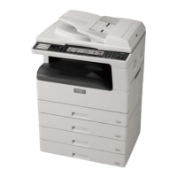
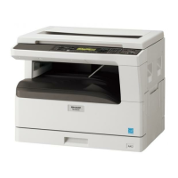
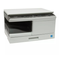
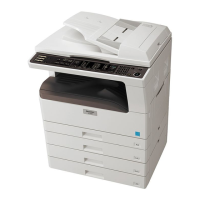
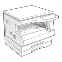
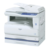
Illustrates how different models and options are configured.
Table detailing which options are available for different machine models.
Details type, composition, speed, job efficiency, and paper feed for copy mode.
Details paper feed, magnification, density, duplexing, and finishing options.
Covers additional functions, other specs, package form, power, and digital performance.
Details platform, supported OS, and printer driver functions.
Details scanner type, resolution, speed, interface, and OS support.
Lists toner, developer, and drum kit part numbers and life for various regions.
Details transport, use, and storage conditions, plus part life.
Explains how to read production dates and lot numbers on cartridges.
Labeled diagram of the exterior parts of the machine.
Labeled diagram showing the internal arrangement of parts.
Details the function of each key and indicator on the operation panel.
Lists and describes the function of various motors, solenoids, and clutches.
Lists and describes the function of various sensors and switches.
Lists and describes the function of various PWBs in the machine.
Illustrates the internal layout from a cross-sectional perspective.
Categorizes and lists various adjustment items with their procedures.
Details developing doctor gap and MG roller position adjustments.
Covers developing bias, grid bias checks, and OC image lead edge adjustment.
Details SPF lead edge, rear edge void, paper off-center, and side edge void adjustments.
Covers duplex adjustments, paper off-center, and main scanning direction distortion.
Details the steps for adjusting main scanning direction distortion balance.
Describes adjustments for distortion in both main and sub scanning directions.
Covers sub scanning distortion adjustment and main scanning magnification ratio adjustment.
Details sub scanning magnification ratio and off-center adjustments.
Covers SPF off-center adjustments and copy mode image density settings.
Describes how to enter and exit the machine's simulation mode.
Lists available simulation codes and their corresponding functions.
Continues the list of available simulation codes and functions.
Explains simulations related to mirror scanning, SPF aging, and sensor checks.
Explains simulations for operation panel checks, fusing lamp, and copy lamp.
Explains simulations for warm-up aging, bias output, and duplex motor operations.
Explains simulations for toner motor, maintenance counters, and jam memory.
Explains simulations for SPF jam counts, scanner counts, and main motor operation.
Explains simulations for auto developer adjustment and size settings.
Explains simulations for auditor settings, duplexing, count modes, and destination.
Explains simulations for toner save mode, CE conformity, auditor setup, and memory capacity.
Explains simulations for side void amount, copy stop function, and life correction settings.
Explains simulations for paper sensor status and fusing temperature settings.
Explains simulations for fusing temperature correction, fan speed, and toner density control.
Explains simulations for transfer current settings and toner density control.
Explains simulations for copy density and copy exposure level adjustments.
Explains simulations for selecting exposure modes like Gamma table, AUTO, and Photo image process.
Explains simulations for SPF exposure correction and image contrast adjustment.
Explains simulations for magnification ratio adjustments and Flash ROM programming.
Explains simulations for adjusting the image lead edge position.
Explains simulations for paper and document off-center adjustments.
Explains simulations for duplex copy memory reverse position and rear edge void adjustments.
Explains simulations for resist adjustment, SPF scan position, and SDRAM access check.
Explains simulations for laser power correction, HSYNC output, shading, and self-print.
Lists main and sub codes for various trouble conditions.
Provides detailed explanations, causes, and solutions for specific trouble codes.
Covers trouble codes related to laser output, copy lamp, and thermistor faults.
Covers trouble codes related to fusing temperature, scanner feed, and return issues.
Covers trouble codes related to motor lock, fan lock, EEPROM errors, and door/cartridge detection.
Provides a comprehensive table of maintenance tasks for various machine parts at different usage intervals.
Explains how to check remaining quantity and provides notes on replacing toner and DV cartridges.
Details disassembly and assembly for high voltage and duplex transport components.
Details disassembly and assembly for optical unit components like table glass, copy lamp, and PWB.
Provides instructions for disassembling and attaching the lens unit, including adjustments.
Details the removal procedures for the fusing unit and thermostat.
Details thermistor installation, heater lamp assembly, and upper heat roller disassembly.
Details lower heat roller assembly and separation pawl procedures.
Details components like ozone filter, cooling fan, and paper exit unit.
Details paper exit sensors, transport rollers, and paper exit rollers.
Details disassembly of MCU, NIC, and installation of the optical frame unit.
Details LSU unit handling and middle frame unit assembly for paper feed.
Details drive unit, PS clutch, paper feed clutch, and connection gear unit procedures.
Details bypass tray transport roller, paper feed, and solenoid procedures.
Details bypass tray transport clutch, pressure plate, and paper feed clutch procedures.
Details disassembly of power unit, PWB, and power switch.
Details developing box, doctor, and MG roller procedures, including adjustments.
Details drum unit, main charger unit, and cleaning blade, with OPC drum servicing notes.
Details Operation PWB, Tray interface PWB, and 2nd tray sensors.
Details 2nd tray transport clutch, roller, feed clutch, and main motor.
Details paper entry and paper empty sensors.
Explains the sequence of operations for paper pickup and transport.
Lists necessary files and notes for preparing the update process.
Details connecting the machine and PC, and initiating the download on the machine.
Guides through setting up the PC software, selecting models, and reconnecting.
Details the steps for installing the hardware driver on Windows XP.
Details the steps for installing the hardware driver on Windows 2000.
Provides specific download procedures for N and DN models, including IP settings.
Illustrates the overall electrical connections and major component interactions.
Shows detailed wiring connections for the operation panel and related components.
Shows detailed wiring connections for LSU, MCU, and sensors.
Shows detailed wiring connections for fusing, cooling fan, and power supply.
Shows detailed wiring connections for SPF interface and sensors.
Shows detailed wiring connections for CS interface and multi-stage components.
Shows detailed wiring connections for USB, NNB, and OP PS interfaces.
Provides important notes and precautions for using lead-free solder and soldering irons.
| Brand | Sharp |
|---|---|
| Model | AR-5623N |
| Category | All in One Printer |
| Language | English |