EasyManua.ls Logo

Sharp AR-5618S User Manual

Sharp AR-5618S
93 pages
To Next Page IconTo Next Page
Page #1 background imageLoading...
Page #1 background image
Parts marked with “ “ are important for maintaining the safety of the set.
Be sure to replace these parts with specified ones for maintaining the safety and performance of the set.
SHARP CORPORATION
This document has been published to be used
for after sales service only.
The contents are subject to change without notice.
CODE : 00ZAR5618/S2E
AR-5618
AR-5618S/5620S
AR-5618N
AR-5618D
AR-5620/5623
AR-5620N/5623N
AR-5620D/5623D
1
1
1
1
[ 1 ] GENERAL . . . . . . . . . . . . . . . . . . . . . . . . . . . . . . . . . . . . . . . . . 1 - 1
[ 2 ] CONFIGURATION. . . . . . . . . . . . . . . . . . . . . . . . . . . . . . . . . . . 2 - 1
[ 3 ] SPECIFICATIONS . . . . . . . . . . . . . . . . . . . . . . . . . . . . . . . . . . . 3 - 1
[ 4 ] CONSUMABLE PARTS . . . . . . . . . . . . . . . . . . . . . . . . . . . . . . . 4 - 1
[ 5 ] EXTERNAL VIEWS AND INTERNAL STRUCTURES . . . . . . . 5 - 1
[ 6 ] ADJUSTMENTS . . . . . . . . . . . . . . . . . . . . . . . . . . . . . . . . . . . . 6 - 1
[ 7 ] SIMULATIONS. . . . . . . . . . . . . . . . . . . . . . . . . . . . . . . . . . . . . . 7 - 1
[ 8 ] TROUBLE CODE LIST . . . . . . . . . . . . . . . . . . . . . . . . . . . . . . . 8 - 1
[ 9 ] MAINTENANCE . . . . . . . . . . . . . . . . . . . . . . . . . . . . . . . . . . . . 9 - 1
[10] DISASSEMBLY AND ASSEMBLY . . . . . . . . . . . . . . . . . . . . . . 10 - 1
[11] OPERATIONAL DESCRIPTIONS . . . . . . . . . . . . . . . . . . . . . . 11 - 1
[12] FLASH ROM VERSION UP PROCEDURE. . . . . . . . . . . . . . . 12 - 1
[13] ELECTRICAL SECTION . . . . . . . . . . . . . . . . . . . . . . . . . . . . . 13 - 1
CONTENTS
MODEL
'11/Jul/22
1
DIGITAL MULTIFUNCTIONAL
SYSTEM
AR-5618/5620/5623
AR-5618S/5620S
AR-5618N/5620N/5623N
AR-5618D/5620D/5623D
1
1
Question and Answer IconNeed help?

Do you have a question about the Sharp AR-5618S and is the answer not in the manual?

Sharp AR-5618S Specifications

General IconGeneral
BrandSharp
ModelAR-5618S
CategoryAll in One Printer
LanguageEnglish

Summary

General Safety and Operational Notes

Warning for Servicing

Fusing area is hot. Exercise care. Do not disassemble laser unit.

Cautions for Servicing

Avoid rapid power cycling. Turn off power before installing supplies. Place on firm surface.

Installation Place Notes

Proper installation prevents damage. Consider condensation from cool to warm places.

Configuration Overview

System Configurations

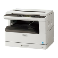
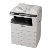
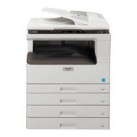
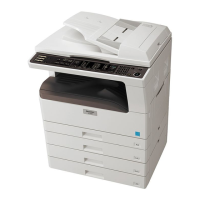
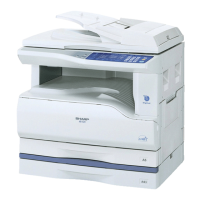
Overview of machine models and compatible options, including feeders and software.

Machine Specifications

Copy Mode and Performance Specs

Details on machine type, paper exit, composition, options, and copy speed.

Component and System Specifications

Specs for multi-copy, warm-up, magnification, density, void width, auto duplex, and paper exit.

Power, Interface, and Scanner Specs

Specs on package form, external view, power, interface, digital performance, printing, and scanner functions.

Consumable Parts Information

Supply System Table

Lists consumable parts (toner, developer, drum kits) by region and their specifications.

Environmental and Storage Conditions

Specifies transport, use, and storage conditions for optimal performance and longevity.

Production Number Identification

Explains how to interpret production and lot numbers on toner and drum cartridges.

External Views and Internal Structures

External Appearance and Operation Section

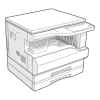
Illustrates external components and describes the operation panel keys and indicators.

Internal Component Identification

Details locations of motors, PWBs, rollers, sensors, switches, and cross-sectional views.

Adjustments

Adjustment Item List

A comprehensive list of all adjustable items, categorized by section and procedure.

Copier Adjustment Procedures

Specific steps for performing copier-related adjustments like developing doctor gap and MG roller positioning.

Simulations

Entering and Cancelling Simulation Mode

Procedures for accessing and exiting the machine's simulation mode for diagnostics and testing.

List of Simulation Codes

A catalog of simulation codes, their main/sub codes, and brief descriptions of functions.

Detailed Simulation Contents

In-depth explanations for various simulation codes and their operational details.

Trouble Code List

Trouble Code Reference

A table listing main and sub codes for identified machine errors.

Trouble Code Details and Remedies

Detailed explanations of trouble codes, including causes and recommended solutions.

Maintenance

Maintenance Schedule Table

Outlines required maintenance tasks (clean, adjust, replace) for various parts at different copy counts.

Maintenance Display and Consumable Notes

Explains checking toner life, developer status, and replacement notes via the machine's display.

Disassembly and Assembly Procedures

High Voltage, Duplex Transport, and Optical Sections

Procedures for disassembling high voltage, duplex transport, optical units, lens, and wire.

Fusing Section Components

Steps for disassembling the fusing unit, its heater lamp, rollers, thermistor, and separation pawls.

Paper Exit and Related Components

Instructions for disassembling the paper exit section, including fans, sensors, rollers, and ozone filter.

Main Control and Interface Units

Procedures for removing MCU/NIC, Optical Frame Unit, and LSU components.

Paper Feed and Transport Systems

Steps for disassembling tray paper feed, drive units, clutches, rollers, bypass tray, and connection gears.

Power, Developing, and Process Sections

Instructions for disassembling the power supply, developing unit, and process section components.

Other Components and Sensors

Procedures for disassembling miscellaneous parts like PWBs, motors, and sensors not covered elsewhere.

Operational Descriptions

Paper Feed Operation

Explains the operational sequence of paper pickup, transport, and feed mechanisms.

Flash ROM Version Up Procedure

Preparation for Firmware Update

Outlines the necessary files and initial setup for the firmware update process.

Download Procedure Steps

Detailed steps for connecting the PC to the machine and initiating the firmware download.

Installation Procedure

Instructions for installing the maintenance tool driver on Windows XP and 2000.

Model-Specific Download Procedures

Specific download procedures for AR-5618N/5620N/5623N models, including IP address setup.

Electrical Section

Block Diagram of Electrical Systems

A high-level overview of the machine's electrical components and their interconnections.

Actual Wiring Diagrams

Detailed wiring diagrams illustrating the physical connections between components and PWBs.

Lead-Free Solder Notes

Note for Lead-Free Solder Thread Usage

Guidelines for using appropriate solder thread and iron when working with lead-free solder.

Notes for Soldering Work

Precautions and best practices for soldering with lead-free solder, including tip maintenance.

Related product manuals