EasyManua.ls Logo

Sharp AR-5620S

Sharp AR-5620S
93 pages
To Next Page IconTo Next Page
Loading...
Parts marked with “ “ are important for maintaining the safety of the set.
Be sure to replace these parts with specified ones for maintaining the safety and performance of the set.
SHARP CORPORATION
This document has been published to be used
for after sales service only.
The contents are subject to change without notice.
CODE : 00ZAR5618/S2E
AR-5618
AR-5618S/5620S
AR-5618N
AR-5618D
AR-5620/5623
AR-5620N/5623N
AR-5620D/5623D
1
1
1
1
[ 1 ] GENERAL . . . . . . . . . . . . . . . . . . . . . . . . . . . . . . . . . . . . . . . . . 1 - 1
[ 2 ] CONFIGURATION. . . . . . . . . . . . . . . . . . . . . . . . . . . . . . . . . . . 2 - 1
[ 3 ] SPECIFICATIONS . . . . . . . . . . . . . . . . . . . . . . . . . . . . . . . . . . . 3 - 1
[ 4 ] CONSUMABLE PARTS . . . . . . . . . . . . . . . . . . . . . . . . . . . . . . . 4 - 1
[ 5 ] EXTERNAL VIEWS AND INTERNAL STRUCTURES . . . . . . . 5 - 1
[ 6 ] ADJUSTMENTS . . . . . . . . . . . . . . . . . . . . . . . . . . . . . . . . . . . . 6 - 1
[ 7 ] SIMULATIONS. . . . . . . . . . . . . . . . . . . . . . . . . . . . . . . . . . . . . . 7 - 1
[ 8 ] TROUBLE CODE LIST . . . . . . . . . . . . . . . . . . . . . . . . . . . . . . . 8 - 1
[ 9 ] MAINTENANCE . . . . . . . . . . . . . . . . . . . . . . . . . . . . . . . . . . . . 9 - 1
[10] DISASSEMBLY AND ASSEMBLY . . . . . . . . . . . . . . . . . . . . . . 10 - 1
[11] OPERATIONAL DESCRIPTIONS . . . . . . . . . . . . . . . . . . . . . . 11 - 1
[12] FLASH ROM VERSION UP PROCEDURE. . . . . . . . . . . . . . . 12 - 1
[13] ELECTRICAL SECTION . . . . . . . . . . . . . . . . . . . . . . . . . . . . . 13 - 1
CONTENTS
MODEL
'11/Jul/22
1
DIGITAL MULTIFUNCTIONAL
SYSTEM
AR-5618/5620/5623
AR-5618S/5620S
AR-5618N/5620N/5623N
AR-5618D/5620D/5623D
1
1
Question and Answer IconNeed help?

Do you have a question about the Sharp AR-5620S and is the answer not in the manual?

Sharp AR-5620S Specifications

General IconGeneral
FunctionsPrint, Copy, Scan, Fax
Print TechnologyLaser
Print Resolution600 x 600 dpi
Copy Resolution600 x 600 dpi
Scan Resolution600 x 600 dpi
Fax Speed33.6 Kbps
Paper Capacity250 sheets
Paper Capacity (Standard)250 sheets
Max Paper SizeA4
InterfaceUSB 2.0
ConnectivityUSB
Memory128 MB
Dimensions18.5 x 19.3 x 15.4 inches
Weight49.5 lbs
TypeAll in One Printer
Print Speed20 ppm
Copy Speed20 cpm

Summary

General Safety Cautions

Laser Radiation Safety

Specific instructions to avoid laser beam exposure during servicing operations.

Radio Interference Warning

Warning about potential radio interference in household/office environments.

Battery Replacement Safety

Battery Replacement Precautions

Safety precautions for handling and replacing batteries in multiple languages.

Battery Disposal Instructions

Instructions for proper disposal of used batteries according to manufacturer guidelines.

General Information and Servicing Notes

Servicing Notes and Pictograms

Pictograms, warnings, and precautions for servicing the machine.

Servicing Cautions

Specific guidelines and precautions to follow during servicing operations.

Installation Place Recommendations

Guidelines for selecting an appropriate location for machine installation and ventilation.

Configuration and System Overview

System Configuration Diagram

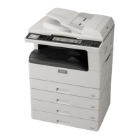
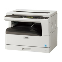
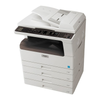
Diagram showing various machine models and optional units.

Option Compatibility

Table detailing which options are available for specific machine models.

Technical Specifications

Copy Mode Specifications

Details on machine types, copy speed, job efficiency, and options.

Paper Feed Specifications

Information on paper capacity, size detection, and type settings.

Machine Specifications Details

Feedable Paper and Magnification

Lists paper sizes/types and settings for copy magnification ratios.

Copy Density and Duplexing

Settings for copy density, gradation, and auto duplex capabilities.

Additional Machine Specifications

Additional Functions and Other Specs

Details on features like APS, E-sort, and photoconductor type.

Power Source and Consumption

Information on voltage, frequency, and power usage.

Digital Performance Specs

Details on resolution, gradation, and memory.

Printing Function Specifications

Platform and OS Support for Printing

Lists supported platforms and operating systems for printing functions.

Printer Driver Functions (SPLC)

Details on various print functions and settings available via the driver.

Scanner Function Specifications

Scanner System and Resolution

Specifications for scan system, resolution, and output data.

Consumable Parts by Region

Consumables - SouthCentral America

Lists toner, developer, and drum kit for this region.

Consumables - Brazil

Lists consumable parts for Brazil.

Consumables - Europe

Lists consumable parts for Europe.

Consumables - AustraliaNew Zealand

Lists consumable parts for Australia/New Zealand.

Consumables - Middle EastAfricaOthers

Lists consumables for Middle East, Africa, Israel, Philippines, Others.

Consumables - Taiwan

Lists consumable parts for Taiwan.

Consumables and Environmental Conditions

Consumables - AsiaThailandHong Kong

Lists consumable parts for Asia (Except above)/Thailand/Hong Kong.

Environmental Conditions

Details transport, use, and storage conditions for the machine.

Consumable Parts Identification

Toner Cartridge Production Number

Explains the date of production label on toner cartridges.

Drum Cartridge Lot Number

Details the 10-digit lot number on drum cartridges.

Machine Views and Components

External Appearance Overview

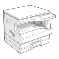
Labeled diagram showing the external parts of the machine.

Internal Components Overview

Labeled diagrams of major internal parts.

Operation Panel and Controls

Operation Panel Layout and Key Functions

Explains the function of each key and indicator on the operation panel.

Internal Components - Motors and Solenoids

Motors, Solenoids, and Clutches

Lists and describes the function of various motors and solenoids.

Internal Components - Sensors and Switches

Sensors and Switches Identification

Lists and describes the function of various sensors and switches.

Internal Components - Printed Wiring Boards

PWB Unit Identification and Functions

Lists and describes the function of various Printed Wiring Boards (PWBs).

Internal Components - Cross-Sectional Views

Cross-Sectional View of Internal Parts

Labeled diagrams showing the arrangement of internal parts.

Adjustments - Process Section

Adjustment Item List Overview

Overview of all adjustable items and their corresponding procedures.

Developing Doctor Gap Adjustment

Step-by-step guide to adjust the developing doctor gap.

Adjustments - Bias Checks and Image Position

Developing and Grid Bias Voltage Checks

Procedures to check the developing and grid bias voltages.

OC Image Lead Edge Position Adjustment

Procedure for adjusting the OC image lead edge position.

Adjustments - Image Position and SPF

Paper Lead Edge and Print Start Position Adjustments

Adjustments for paper lead edge and print start position.

SPF Image Lead Edge Position Adjustment

Procedure for adjusting SPF image lead edge position.

Adjustments - Duplex and Scanning Direction

Duplex Mode Off-Center and Void Area Adjustments

Adjustments for duplex off-center and side void.

Main Scanning Direction Distortion Balance

Procedure to balance distortion in the main scanning direction.

Adjustments - Scanning Direction Distortion

Main Scanning Direction Distortion Adjustment

Step-by-step instructions for adjusting main scanning direction distortion.

Adjustments - Distortion and Magnification

Main Scanning Direction Distortion Measurement

How to measure and adjust main scanning direction distortion.

Sub Scanning Direction Distortion Adjustment

Procedure for adjusting sub scanning direction distortion.

Adjustments - Distortion and Magnification Ratios

Sub Scanning Direction Distortion Measurement

How to measure and adjust sub scanning direction distortion.

Main Scanning Direction Magnification Ratio

Procedure for adjusting magnification ratio in the main scanning direction.

Adjustments - Magnification and Off-Center

Sub Scanning Magnification Ratio Adjustment

Procedures for adjusting magnification ratio in sub scanning direction for OC and RSPF modes.

Off-Center Adjustment (OC Mode)

Procedure for adjusting off-center in OC mode.

Adjustments - Off-Center and Density

SPF Off-Center Adjustment Procedure

Procedure for adjusting off-center in SPF mode.

Image Density Adjustment (Copy Mode)

Procedure for adjusting image density in copy mode.

Simulations - Access and List

Entering and Canceling Simulation Mode

How to access and exit simulation modes.

List of Simulation Codes

A comprehensive list of simulation codes and their functions.

Simulation Details - Magnification and Flash ROM

Simulations: Magnification Ratio

Explains simulations related to magnification ratio adjustments.

Simulations: Flash ROM Program Writing

Details on Flash ROM writing procedures.

Simulations: Image Lead Edge Adjustment

Explains simulations for image lead edge adjustment.

Simulation Details - SPF Operations

Simulations: SPF Aging and Sensor Status

Explains simulations for SPF aging and sensor status.

Simulations: SPF Motor and Solenoid Checks

Explains simulations for SPF motor and solenoid checks.

Simulation Details - Panel and Fusing Checks

Simulations: Operation Panel and Fusing Lamp Checks

Explains simulations for checking operation panel and fusing lamp.

Simulations: Paper Feed SolenoidClutch

Explains simulations for paper feed solenoid/clutch operations.

Simulation Details - Warm-up and Bias

Simulations: Warm-up Aging and Jam

Explains simulations for warm-up aging.

Simulations: Developing Bias and Main Charger

Explains simulations for developing bias and main charger output.

Simulation Details - Maintenance and ROM

Simulations: Maintenance Counters and Settings

Explains simulations for maintenance counters and settings.

Simulations: P-ROM Version and Trouble Memory

Explains simulations for P-ROM version and trouble memory.

Simulation Details - Counter Clearing and Checks

Simulations: Counter Clearing Procedures

Explains simulations for clearing various counters.

Simulations: Developer and Motor Checks

Explains simulations for developer and motor checks.

Simulation Details - Settings and Conformity

Simulations: Auditor and Duplex Settings

Explains simulations for auditor and duplex settings.

Simulations: Size Setting and Machine Condition

Explains simulations for size setting and machine condition check.

Simulation Details - Count Mode and Toner Save

Simulations: Count Mode and Destination Setting

Explains simulations for count mode and destination setting.

Simulations: Toner Save Mode and CE Mark

Explains simulations for toner save mode and CE mark conformity.

Simulation Details - Stop Cancellations and Timing

Simulations: Auditor Setup and Stop Cancellations

Explains simulations for auditor setup and stop cancellations.

Simulations: Memory Capacity and Transfer Timing

Explains simulations for memory capacity and transfer ON/OFF timing.

Simulation Details - Void and Temporary Stop

Simulations: Side Void Amount and Copy Temporary Stop

Explains simulations for side void amount and temporary stop.

Simulations: Life Correction and Toner End

Explains simulations for life correction and toner end operations.

Simulation Details - Sensors and Fusing

Simulations: Paper Sensor Status and Developing Counter

Explains simulations for paper sensor status and developing counter clear.

Simulations: Fusing Temperature Settings

Explains simulations for fusing temperature settings.

Simulation Details - Fusing Correction and Feed Cycle

Simulations: Fusing Correction and Postcard Feed

Explains simulations for fusing temperature correction and postcard feed cycle.

Simulations: Fusing Fan Speed and Paper Interval

Explains simulations for fusing fan speed and paper interval control.

Simulation Details - Toner Density and Transfer Current

Simulations: Toner Density Control

Explains simulations for toner density control.

Simulations: Transfer Current Setting

Explains simulations for transfer current setting.

Simulation Details - Copy Density and Exposure Level

Simulations: Copy Density Adjustment

Explains simulations for copy density adjustment.

Simulations: Copy Exposure Level (Text)

Explains simulations for copy exposure level adjustment for text mode.

Simulation Details - Exposure Level and Mode

Simulations: Copy Exposure Level (Photo)

Explains simulations for copy exposure level adjustment for photo mode.

Simulations: Exposure Mode Setting

Explains simulations for setting exposure modes.

Simulation Details - SPF Exposure and Contrast

Simulations: SPF Exposure Correction

Explains simulations for SPF exposure correction.

Simulations: Image Contrast Adjustment

Explains simulations for image contrast adjustment.

Simulations: AUTO Exposure Limit

Explains simulations for AUTO exposure limit setting.

Simulation Details - Sharpness and Magnification

Simulations: Image Sharpness Adjustment

Explains simulations for image sharpness adjustment.

Simulations: MainSub Scanning Magnification

Explains simulations for adjusting magnification ratios.

Simulation Details - SPF Magnification and ROM Writing

Simulations: SPFRSPF Sub Scanning Magnification

Explains simulations for SPF/RSPF sub scanning magnification ratio.

Simulations: Flash ROM Program Writing (MCU)

Explains simulations for Flash ROM writing via MCU.

Simulations: Flash ROM Program Writing (NNB)

Explains simulations for Flash ROM writing via NNB.

Simulation Details - Image and Paper Alignment

Simulations: Image Lead Edge Adjustment

Explains simulations for image lead edge adjustment.

Simulations: SPFRSPF Copy Lead Edge Position

Explains simulations for SPF/RSPF copy lead edge position.

Simulation Details - Paper and Document Alignment

Simulations: Paper Off-Center Adjustment

Explains simulations for paper off-center adjustment.

Simulations: Document Off-Center Adjustment

Explains simulations for document off-center adjustment.

Simulation Details - Duplex Copy Adjustments

Simulations: Duplex Memory Reverse Position

Explains simulations for duplex copy memory reverse position.

Simulations: Duplex Rear Edge Void Adjustment

Explains simulations for duplex rear edge void adjustment.

Simulation Details - Resist and SPF Scanning

Simulations: Resist Amount Adjustment

Explains simulations for resist amount adjustment.

Simulations: SPF Scanning Position Automatic

Explains simulations for SPF scanning position adjustment.

Simulations: SPF Document Scan Position Select

Explains simulations for SPF document scan position select.

Simulation Details - SDRAM, Laser, and HSYNC

Simulations: SDRAM Access Check and Laser Power

Explains simulations for SDRAM check and laser power correction.

Simulations: HSYNC Output and Shading Check

Explains simulations for HSYNC output and shading checks.

Simulation Details - SPF Correction and Self Print

Simulations: SPF Automatic Correction

Explains simulations for SPF automatic correction.

Simulations: Self Print

Explains simulations for self-print.

Trouble Codes and Details

Trouble Codes: E7, F2, H2

Details trouble codes related to E7, F2, and H2.

Trouble Codes Details

Trouble Codes: H3, H5, L1

Details trouble codes related to H3, H5, and L1.

Trouble Codes Details

Trouble Codes: L3, L4, U2

Details trouble codes related to L3, L4, and U2.

Maintenance Schedule and Procedures

Maintenance Table - Drum, Developing, Optical

Maintenance schedule for drum, developing, and optical parts.

Maintenance Schedule Details

Maintenance Table - LSU, Paper Feed, Fusing, Drive

Maintenance schedule for LSU, paper feed, fusing, and drive parts.

Maintenance Table - Paper Exit

Maintenance schedule for paper exit parts.

Maintenance Schedule and Display System

Maintenance Table - Document Transport, Cassette Feed

Maintenance schedule for document transport and cassette feed parts.

Maintenance Display System

How to check toner and developer remaining quantity.

Consumable Replacement Notes

Toner Cartridge Replacement Precautions

Precautions for replacing the toner cartridge.

Developer Cartridge Handling Precautions

Precautions for handling the developer cartridge.

DV Seal Attachment Procedure

Instructions for attaching the DV seal.

Disassembly and Assembly - General

General Warning and Section List

Precaution before disassembly and list of components.

High Voltage and Duplex Transport Section

Disassembly instructions for high voltage and duplex transport.

Charger Wire Installation

Specific instructions for installing the charger wire.

Disassembly - Optical Section

Optical Section: Table Glass and Copy Lamp Unit

Procedures for disassembling table glass and copy lamp unit.

Optical Section: Inverter PWB and Copy Lamp

Procedures for disassembling inverter PWB and copy lamp.

Disassembly - Lens Unit and Fusing Section

Optical Section: Lens Unit Disassembly

Procedures for disassembling the lens unit.

Fusing Section: Fusing Unit Removal

Procedure for removing the fusing unit.

Fusing Section: Thermostat Replacement

Procedure for replacing the thermostat.

Disassembly - Fusing and Paper Exit Sections

Fusing Section: Thermistor and Heater Lamp

Procedures for disassembling thermistor and heater lamp.

Fusing Section: Upper Heat Roller

Procedure for disassembling the upper heat roller.

Paper Exit Section: Ozone Filter and Cooling Fan

Procedures for removing ozone filter and cooling fan.

Disassembly - Paper Exit Section Components

Paper Exit Section: Paper Exit Unit

Procedures for disassembling the paper exit unit.

Paper Exit Section: Sensors

Procedures for disassembling paper exit and duplex sensors.

Paper Exit Section: Rollers

Procedures for disassembling transport and paper exit rollers.

Disassembly - MCUNIC and Optical Frame

MCUNIC Disassembly: MCU PWB

Procedures for disassembling the MCU PWB.

MCUNIC Disassembly: NIC PWB

Procedures for disassembling the NIC PWB.

Optical Frame Unit Disassembly

Procedure for disassembling the optical frame unit.

Disassembly - LSU and Tray Paper Feed

LSU Unit Disassembly and Adjustments

Procedures for LSU unit removal and adjustments.

Tray Paper Feed Section: Middle Frame Unit

Procedure for disassembling the middle frame unit.

Disassembly - Paper Feed Components

Tray Paper Feed Section: Drive Unit

Procedure for disassembling the drive unit.

Tray Paper Feed Section: PS ClutchResist Roller

Procedure for disassembling the PS clutch/resist roller.

Tray Paper Feed Section: Paper Feed ClutchRoller

Procedure for disassembling the paper feed clutch/roller.

Disassembly - Bypass Tray Section

Bypass Tray Section: Transport RollerPaper Feed Roller

Procedures for disassembling bypass tray rollers.

Bypass Tray Section: Paper Feed

Procedures for disassembling bypass tray paper feed components.

Bypass Tray Section: Bypass Tray Solenoid

Procedures for disassembling the bypass tray solenoid.

Disassembly - Bypass Tray Components

Bypass Tray Section: Transport Clutch

Procedures for disassembling bypass tray transport clutch.

Bypass Tray Section: Pressure Plate Unit

Procedures for disassembling the pressure plate unit.

Bypass Tray Section: Paper Feed Clutch

Procedures for disassembling bypass tray paper feed clutch.

Disassembly - Power Section Components

Power Section: Power Unit

Procedures for disassembling the power unit.

Power Section: High Voltage P.W.B.

Procedures for disassembling the high voltage PWB.

Power Section: Power P.W.B.

Procedures for disassembling the power PWB.

Power Section: Power Switch

Procedures for disassembling the power switch.

Disassembly - Developing Section Components

Developing Section: Developing Box

Procedures for disassembling the developing box.

Developing Section: Developing Doctor

Procedures for disassembling the developing doctor.

Developing Section: MG Roller

Procedures for disassembling the MG roller and its adjustment.

Disassembly - Process Section Components

Process Section: Drum Unit and OPC Drums

Procedures for disassembling the drum unit and handling OPC drums.

Process Section: Main Charger Unit

Procedures for disassembling the main charger unit.

Process Section: Cleaning Blade

Procedures for disassembling the cleaning blade.

Disassembly - Other Section Components

Others: Operation P.W.B.

Procedures for disassembling the operation PWB.

Others: Tray Interface P.W.B.

Procedures for disassembling the tray interface PWB.

Disassembly - Other Section Components (Sensors, Motor)

Others: 2 nd Tray Sensors and Clutches

Procedures for disassembling sensors and clutches.

Others: 2 nd Tray Transport Roller

Procedures for disassembling transport roller.

Others: 2 nd Tray Paper Feed Clutch

Procedures for disassembling paper feed clutch.

Others: Main Motor Disassembly

Procedures for disassembling the main motor.

Disassembly - Other Section Components (Sensors)

Others: Paper Entry Sensor

Procedures for disassembling the paper entry sensor.

Others: Paper Empty Sensor

Procedures for disassembling the paper empty sensor.

Operational Descriptions - Paper Feed

Paper Feed Operation Mechanism

Explains how the paper feed mechanism operates.

Flash ROM Version Up Procedure - Preparation

Firmware Update Preparation

Necessary files and steps before starting the update.

Download Procedure: Machine and PC Setup

Steps for connecting the machine and PC and setting up software.

Flash ROM Version Up Procedure - Download

Download Procedure: File Specification and Completion

Steps for specifying download files and confirming completion.

Installation Procedure: USB Driver

Steps for installing the USB driver.

Flash ROM Version Up Procedure - Windows XP

Installation Procedure: Windows XP Driver Setup

Step-by-step guide for driver installation on Windows XP.

Flash ROM Version Up Procedure - Windows 2000

Installation Procedure: Windows 2000 Driver Setup

Step-by-step guide for driver installation on Windows 2000.

Flash ROM Version Up Procedure - Model Specific

Download Procedures for AR-5618 N5620 N5623 N

Detailed steps for downloading firmware to these specific models.

Electrical Section - Block Diagram

Electrical System Block Diagram

Overall block diagram of the machine's electrical components.

Electrical Section - Actual Wiring Diagrams

Actual Wiring Diagram Part 1

Detailed wiring connections for various components.

Electrical Section - Actual Wiring Diagrams

Actual Wiring Diagram Part 2

Detailed wiring connections for various components.

Electrical Section - Actual Wiring Diagrams

Actual Wiring Diagram Part 3

Detailed wiring connections for various components.

Electrical Section - Actual Wiring Diagrams

Actual Wiring Diagram Part 4

Detailed wiring connections for various components.

Electrical Section - Actual Wiring Diagrams

Actual Wiring Diagram Part 5

Detailed wiring connections for various components.

Electrical Section - Actual Wiring Diagrams

Actual Wiring Diagram Part 6

Detailed wiring connections for various components.

Related product manuals