Do you have a question about the Sharp AR-5620N and is the answer not in the manual?
Information regarding the product's classification as a Class 1 laser product and associated risks.
Warning about potential radio interference if operated in household or office environments.
Safety instructions for replacing and disposing of batteries, including explosion risks.
Guidelines for safe servicing, including hot areas and laser safety precautions.
Recommendations for machine placement, ventilation, and environmental conditions.
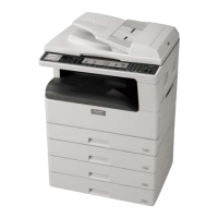
Overview of system configurations, models, and available options like feeders and network kits.
Details on copy mode, machine type, paper exit, and core composition.
Performance metrics like job efficiency, copy speed, and first copy time.
Details on document handling capabilities and paper feed specifications.
Information on feedable paper types, magnification ratios, and copy density.
Specifications for void width, auto duplex, paper exit/finishing options.
Details on additional functions, external views, power source, and digital performance.
Specifications related to printing functions, OS support, and printer driver details.
Technical specifications for the scanner function, including resolution and interface.
Lists consumable parts (toner, developer, drum) and their life for various regions.
Details on transport, use, and storage conditions for the machine.
Information on consumable life, production numbers, and cartridge details.
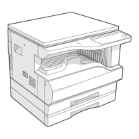
Identifies external parts and components of the machine.
Labels and identifies key internal components and assemblies.
Explains the operation panel layout, keys, and indicators.
Lists and describes the function of various motors, solenoids, and clutches.
Identifies and explains the function of sensors and switches.
Identifies and describes the function of various PWB units.
Illustrates a cross-sectional view of the machine's internal workings.
Lists adjustment items categorized by section (Process, Mechanism, Image Density).
Details on developing bias, grid bias voltage checks, and image position adjustment.
Procedures for adjusting image position, void amounts, and distortion.
Further details on adjusting distortion and void areas for image quality.
Procedures for adjusting main and sub scanning direction distortions.
Steps for adjusting magnification ratios in scanning directions.
Procedures for adjusting magnification ratios and off-center positions.
Details on off-center adjustments and initial image density adjustments.
Procedures for SPF off-center adjustment and copy mode density adjustments.
Procedures for entering and exiting simulation modes.
A comprehensive list of simulation codes and their functions.
Detailed descriptions of various simulation modes and their operations.
Further details on simulation modes related to sensors and motors.
Descriptions of simulations for operation panel checks, fusing, and paper feed solenoids.
Details on simulations for warm-up, aging, bias, charger outputs, and motor functions.
Covers simulations for toner motor, trouble cancel, maintenance counters, and displays.
Details on simulations for clearing counters, memory checks, and P-ROM versions.
Covers simulations for size setting, auditor, duplex settings, and machine condition checks.
Details on simulations for toner save, CE mark, auditor setup, and stop cancels.
Covers simulations for memory capacity, transfer timing, and toner density control.
Details on side void amount, copy temporary stop, life correction, and toner end settings.
Covers simulations for paper sensor status, developing counter, and fusing temperature settings.
Details on fusing temperature correction, postcard feed, and fusing fan speed settings.
Covers simulations for toner density control and transfer current settings.
Details on copy density and copy exposure level adjustments for text.
Covers copy exposure level adjustment for photo and exposure mode settings.
Details on SPF exposure correction, image contrast, AUTO exposure limits, and sharpness.
Covers magnification ratio adjustments and Flash ROM programming.
Details on image lead edge and copy lead edge position adjustments.
Covers paper off-center and document off-center adjustments.
Details on duplex copy memory reverse position and rear edge void adjustments.
Covers resist amount adjustment and SPF scanning position settings.
Details on laser power correction, HSYNC, shading, SPF auto correction, and self print.
Lists main trouble code categories and their associated sub codes.
Explains specific trouble codes, causes, and remedies for errors like LSU trouble.
Details on trouble codes related to ATC sensor, toner supply, CRUM, and thermistors.
Explains trouble codes for heat roller, scanner feed, and scanner return issues.
Details on trouble codes for motor lock, fusing fan, PSFAN, polygon motor, EEPROM, and door sensors.
A table detailing maintenance tasks, intervals, and parts for different units.
Explains the maintenance display, toner/developer life, and DV seal attachment.
Guidelines for replacing toner and developer cartridges safely.
Safety warning to remove the power cord before disassembly.
Procedures for disassembling high voltage and duplex transport sections.
Instructions for installing the charger wire correctly.
Details on disassembling the optical section, including table glass and copy lamp unit.
Procedures for disassembling and adjusting the lens unit.
Instructions for handling wires and removing the fusing unit and thermostat.
Procedures for disassembling thermistors, heater lamps, and the upper heat roller.
Instructions for disassembling the lower heat roller and separation pawls.
Details on separation pawls and disassembly of ozone filter, cooling fan, and paper exit unit.
Procedures for disassembling paper exit sensors, transport rollers, and exit rollers.
Instructions for disassembling MCU/NIC units and the optical frame unit.
Procedures for disassembling the LSU unit and the middle frame of the paper feed section.
Instructions for disassembling drive units, clutches, and gear units.
Procedures for disassembling bypass tray transport rollers, paper feed, and solenoid.
Instructions for disassembling bypass tray transport clutch, pressure plate, and paper feed clutch.
Procedures for disassembling the power unit, high voltage PWB, power PWB, and power switch.
Instructions for disassembling the developing box, doctor, and MG roller.
Procedures for disassembling the drum unit, main charger unit, and cleaning blade.
Instructions for disassembling operation PWB and tray interface PWB.
Procedures for disassembling 2nd tray sensors, clutches, rollers, and the main motor.
Instructions for disassembling paper entry and paper empty sensors.
Explains the process of paper pickup, feed, and transportation during operation.
Necessary files and steps for preparing the upgrade process.
Steps for downloading the firmware to the machine and PC.
Instructions for installing the maintenance program on Windows XP.
Instructions for installing the maintenance program on Windows 2000.
Specific steps for downloading firmware to N/N models.
Shows the interconnections between major electronic components and PWBs.
Detailed wiring diagram showing connections between components and PWBs.
Continues the detailed wiring diagram for various units and connections.
Further details of the wiring diagram, showing PWB interconnections and component wiring.
Illustrates wiring for SPF interface, sensors, and motors.
Shows wiring for CS interface PWBs and various unit connections.
Final part of the wiring diagram, showing USB, NNB, and PS connections.
Guidance on using lead-free solder thread and soldering irons for repairs.
Precautions for soldering work, including tip care and heat management.
| Print Technology | Laser |
|---|---|
| Print Speed | 20 ppm |
| Print Resolution | 600 x 600 dpi |
| Network Connectivity | Ethernet |
| Scan Resolution | 600 x 600 dpi |
| Copy Speed | 20 cpm |
| Functions | Print, Copy, Scan |
| Max Paper Size | A3 |
| Interface | USB 2.0 |
| Dimensions | 599 x 612 x 511 mm |
| Paper Size | A4 |
| Memory | 64 MB |
| Paper Capacity | 350 sheets |