EasyManua.ls Logo

Sharp CD-C1W

Sharp CD-C1W
72 pages
To Next Page IconTo Next Page
Loading...
CD-C1W,CP-C1W
– 1 –
Page
SAFETY PRECAUTION FOR SERVICE MANUAL ................................................................................................................ 2
VOLTAGE SELECTION .......................................................................................................................................................... 2
AC POWER SUPPLY CORD AND AC PLUG ADAPTOR ...................................................................................................... 2
SPECIFICATIONS ................................................................................................................................................................. 3
NAMES OF PARTS ............................................................................................................................................................... 4
OPERATION MANUAL .......................................................................................................................................................... 6
DISASSEMBLY...................................................................................................................................................................... 8
REMOVING AND REINSTALLING THE MAIN PARTS ....................................................................................................... 11
ADJUSTMENT ..................................................................................................................................................................... 12
TEST MODE ......................................................................................................................................................................... 14
NOTES ON SCHEMATIC DIAGRAM .................................................................................................................................. 16
TYPES OF TRANSISTOR AND LED.................................................................................................................................... 16
BLOCK DIAGRAM ............................................................................................................................................................... 17
SCHEMATIC DIAGRAM/WIRING SIDE OF P.W.BOARD ................................................................................................... 20
WAVEFORMS OF CD CIRCUIT .......................................................................................................................................... 42
TROUBLE SHOOTING ........................................................................................................................................................ 43
FUNCTION TABLE OF IC.................................................................................................................................................... 46
FL SEGMENT ...................................................................................................................................................................... 55
PARTS GUIDE/EXPLODED VIEW
CONTENTS
CD-C1W
CP-C1W
SERVICE MANUAL
SHARP CORPORATION
No. YS792CDC1W///
• In the interests of user-safety the set should be restored to its original
condition and only parts identical to those specified should be used.
This document has been published to be used
for after sales service only.
The contents are subject to change without notice.
SRS technology Licensed from SRS Labs. SRS technol-
ogy holds the following patents: U.S. Patent No.
4,748,669 and U.S. Patent No. 4,841,572.
, the SRS Logo () and the
are registered trademarks of SRS Labs, Inc. in the United
States.
SOUND RETRIEVAL SYSTEM
Dolby noise reduction manufactured under license from
Dolby Laboratories Licensing Corporation.
"DOLBY" and the double-D symbol are trademarks
of Dolby Laboratories Licensing Corporation.
Question and Answer IconNeed help?

Do you have a question about the Sharp CD-C1W and is the answer not in the manual?

Sharp CD-C1W Specifications

General IconGeneral
BrandSharp
ModelCD-C1W
CategorySpeaker System
LanguageEnglish

Summary

Safety Precautions for Service

Warnings and Cautions on Laser Safety

Critical warnings and cautions about laser emission hazards and eye protection during servicing.

Voltage Selection Procedure

Instructions for selecting the correct AC voltage for the unit using the voltage selector.

Technical Specifications

CD-C1 W Model Specifications

Detailed technical specs for the CD-C1W, covering power, dimensions, output, and audio outputs.

CP-C1 W Model Specifications

Detailed technical specs for the CP-C1W, including speaker, tuner, and cassette deck.

Names of Parts Identification

Front Panel Controls and Indicators

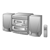
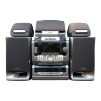
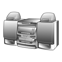
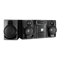
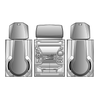
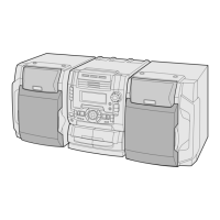
Identifies all controls, buttons, and indicators located on the front panel of the unit.

Rear Panel Connections and Terminals

Identifies all input/output sockets, terminals, and connectors located on the rear panel.

Remote Control Functions and Layout

Identifies all buttons and functions of the remote control transmitter.

CP-C1 W Speaker System Components

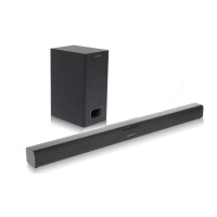
Identifies speaker drivers, ducts, and terminals for the CP-C1W model.

Clock Setting and Operation Guide

Clock Adjustment and Power Failure Handling

Step-by-step guide for setting the clock and managing time display during power outages.

System Reset and Remote Control Usage

Microcomputer Reset Procedure and Notes

Instructions for resetting the system's microcomputer and notes on its operation.

Remote Control Usage Guidelines

Important notes and precautions for using the remote control effectively.

Disassembly and Component Removal

General Disassembly Safety Precautions

Crucial safety precautions and notes to follow before and during disassembly.

CD-C1 W Disassembly Steps

Detailed steps for disassembling various parts of the CD-C1W model.

CP-C1 W Disassembly Steps

Detailed steps for disassembling various parts of the CP-C1W model.

Main Parts Removal and Reinstallation Guide

CD Mechanism and Pickup Handling

Procedures for removing the CD mechanism, its optical pickup, and related motors.

CD Disc Removal Procedures

Steps to remove a CD from the unit in playback or tray states.

Adjustment Procedures for Mechanisms and Tuner

Mechanism, Tape Section, and Bias Adjustments

Adjustments for tape mechanism, tape section controls, bias current, and frequency.

Playback and Record Sensitivity Calibration

Calibration of playback amplifier sensitivity and record/playback sensitivity.

Tuner Section Adjustment Procedures

AM and FM Signal Tuning and Mute Level Settings

Setting AM IF/RF, FM RF signals, and FM mute level for proper reception.

Test Mode for Tuner Calibration

Procedure to enter test mode for tuner circuit adjustment and calibration.

Test Mode Operations and CD Adjustments

Test Mode Setup and CD Operation Test

Procedures for entering test modes and description of the CD operation test.

CD Automatic Adjustment Features

Overview of automatic adjustment functions like focus offset, tracking offset, and E/F balance.

Automatic Sound Correction Control Explanation

Purpose and Operation of Sound Correction

Explains the purpose and detailed operation of the automatic sound adjustment feature.

Schematic Diagram Notes and Component Codes

Component Identification and Measurement Notes

Explains component codes, voltage measurement notes, and safety remarks for parts.

System Block Diagram Overview (13)

System Block Diagram Overview (23)

System Block Diagram Overview (33)

Troubleshooting Guide for CD Functionality

CD Operation and Tray Malfunctions

Troubleshooting steps for CD operation issues, tray failures, and general function loss.

CD Key and Basic Function Checks

Steps to verify CD key functionality, power, clock, and pickup switch.

CD Operation Key Troubleshooting

Diagnostic steps when CD keys work but playback is problematic, checking servo systems.

Playback Issues with Disc Loaded

Troubleshooting steps when playback only occurs with a disc, checking servo systems.

Tracking, Spindle, and VCO-PLL System Checks

Procedures for checking tracking, spindle motor, VCO-PLL systems, and sound output issues.

VCO-PLL and Sound Output Diagnosis

Diagnosing VCO-PLL system, TOC reading, and no sound output issues.

Integrated Circuit Function Tables

IC1 Servo Amplifier Pin Functions (12)

Pin function table for IC1 Servo Amp. (LA9241M) (Part 1/2).

IC1 Servo Amplifier Pin Functions (22)

Pin function table for IC1 Servo Amp. (LA9241M) (Part 2/2).

IC2 ServoSignal Control Function Details

IC2 ServoSignal Control Pin Functions (12)

Pin function table for IC2 Servo/Signal Control (LC78623K) (Part 1/2).

IC2 ServoSignal Control Pin Functions (22)

Pin function table for IC2 Servo/Signal Control (LC78623K) (Part 2/2).

Microcomputer and Audio Processor Function Details

IC201 System Microcomputer Pin Functions (12)

Pin function table for IC201 System Microcomputer (IX0210AW) (Part 1/2).

IC201 System Microcomputer Pin Functions (22)

Pin function table for IC201 System Microcomputer (IX0207AW) (Part 2/2).

IC501 Audio Processor Pin Functions

Pin function table for IC501 Audio Processor (LC75396N) detailing its terminals.

Display and Control IC Function Details

IC701 FL Driver Pin Functions (12)

Pin function table for IC701 FL Driver & Controller (IX0206AW) (Part 1/2).

IC701 FL Driver Pin Functions (22)

Pin function table for IC701 FL Driver & Controller (IX0206AW) (Part 2/2).

FL Display Segment Assignments

FL Display Pin Assignment Details

Detailed pin assignment table for the FL display segments and their functions.

Component Parts Identification and Notes

Capacitor and Resistor Code Explanations

Explains codes used to identify capacitor and resistor types, values, and tolerances.

Parts Replacement Safety and Handling

Important note regarding the replacement of parts marked with "" for safety and performance.

CD-C1 W Component Parts Reference

Integrated Circuits, Transistors, and Diodes

Lists integrated circuits, transistors, and diodes with their part codes and descriptions.

Capacitors and Resistors (Part 1)

Lists capacitors and resistors with their part codes, values, and descriptions.

Capacitors and Resistors (Part 2)

Continues the list of capacitors and resistors with their part codes, values, and descriptions.

Resistors (Part 3)

Continues the list of resistors with their part codes and values.

Resistors (Part 4)

Continues the list of resistors with their part codes and values.

Resistors (Part 5)

Continues the list of resistors with their part codes and values.

Fuses, Cables, Connectors, and Switches

Lists fuses, cables, connectors, switches, and other miscellaneous parts.

Accessories and Packing Materials

Lists accessories and packing materials like labels, cords, bags, and warranty cards.

Cabinet, Chassis, and Mechanism Parts

Lists cabinet, chassis, CD mechanism, and changer mechanism parts.

Related product manuals