EN-5
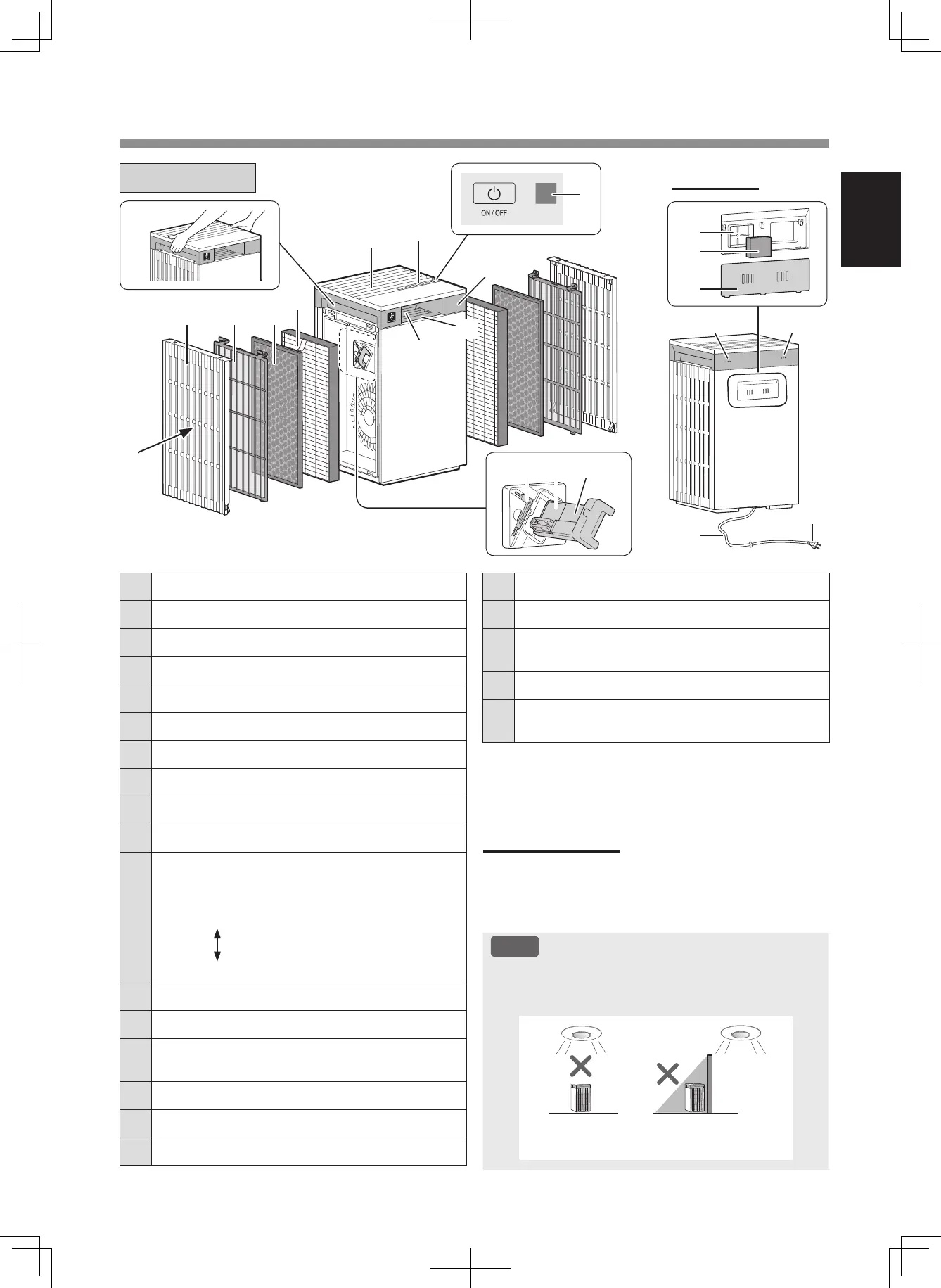
PART NAMES
MAIN BODY
1 Air Inlet
(Left and Right)
2 Side Panel
(Left and Right)
3 Pre-Filter
(Left and Right)
4 Deodorizing Filter
(Left and Right)
5 Micro HEPA Plus Filter
(Left and Right)
6 Handle
(Left and Right)
7
Air Outlet
8 Operation Panel
9 Light Sensor
10 Display
11
Cleanliness Indicator
Indicates the air purity of the room in 5 levels with
color changes.
Clean
Blue
Yellow (Flashing)
Impure
Red (Flashing fast)
12 Air Outlet
(Front)
13 Unit* Cleaning Brush
(Left only)
14
Unit (Plasmacluster Ion Generating Unit)
(Left only)
15 Unit Holder
(Left only)
16 Sensitive Dust Sensor
(Internal)
17
Sensor Filter
Back Side
LIGHT SENSOR
When the Light Control (Display Brightness) is set
to “Auto”, the Display and Cleanliness Indicator will
automatically switch ON or OFF based on room
brightness. (Page 13)
NOTE
Detection range of Light Sensor
Do not install the product in the following places. The
Light Sensor may not sense correctly.
Directly under
a light fixture.
In the shadow
18 Sensor Cover
19 Sensitive Odor Sensor
(Internal)
20
Sensor
(Internal)
Temperature / Humidity
21 Power Cord
22
Power Plug
(Shape of power plug depends on country.)
* The Unit refers to Plasmacluster Ion Generating Unit. (The
same as below.)
14 1513
2 3 4
5
7
8
10
11
9
6
1
12
22
16
17
18
21
19 20