48
LC-30HV4E
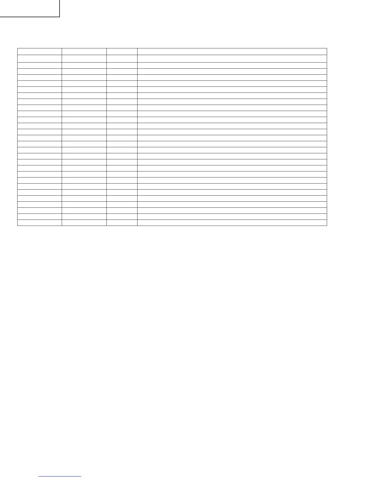
Pin No. Pin Name Type Description
1 BIAS –– ADC bias
2 VRT –– ADC upper limit bias
3 VDD1 –– ADC and DAC power supply (analog system)
4 TESTI1 I TEST Input
5 VSS2 –– ADC GND (analog system)
6 VRB –– Video signal input
7 YCIN I ADC lower limit bias
8 TEST O Reset control and test control before shipping
9 KILLER I Y/C separation and vertical enhancer OFF
10 TESTI2 I TEST Input
11 VDD3 –– Power supply to logic (digital system)
12 VSS3 –– Logic and DRAM GND (digital system)
13 VDD2 –– DRAM power supply (digital system)
14 TESTI3 I TEST Input
15 SCL I I2C BUS clock input
16 SDA I I2C BUS data input
17 MODE1 O MODE1 output
18 TESTOUT I Test input
19 FSC I Clock input
20 VDD4 –– PLL power supply (analog system)
21 VSS4 –– PLL GND (analog system)
22 FIL I VCO control
23 PD O PLL detection output
24 VB2 –– DAC bias 2
25 YOUT O Luminance signal output
26 VSS1 –– DAC GND (analog system)
27 COUT O Color signal output
28 VB1 –– DAC bias 1
ËVHiTC90A69++1Y (ASSY:IC402)
3 Line Digital Comb Filter (NTSC/PAL)
» Pin mapping