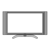
LC-45GD5U
SERVICE MANUAL
MODEL
LC-45GD5U
LCD COLOR TELEVISION
In the interests of user-safety (Required by safety regulations in some countries) the set should be re-
stored to its original condition and only parts identical to those specified should be used.
CONTENTS
Page
» IMPORTANT SERVICE SAFETY PRECAUTION ......................................................................................2
» SPECIFICATIONS ......................................................................................................................................5
» OPERATION MANUAL ...............................................................................................................................6
» DIMENSIONS ...........................................................................................................................................17
» REMOVING OF MAJOR PARTS ..............................................................................................................18
» ADJUSTMENT PROCEDURE..................................................................................................................21
» TROUBLESHOOTING TABLE .................................................................................................................44
» MAJOR IC INFOMATIONS .......................................................................................................................57
» CHASSIS LAYOUT/OVERALL WIRING DIAGRAM .................................................................................60
» SYSTEM BLOCK DIAGRAM ....................................................................................................................62
» DIGITAL BLOCK DIAGRAM .....................................................................................................................64
» MAIN BLOCK DIAGRAM ..........................................................................................................................66
» AV BLOCK DIAGRAM ..............................................................................................................................68
» POWER BLOCK DIAGRAM ..................................................................................................................... 70
» PRINTED WIRING BOARD ASSEMBLIES ..............................................................................................72
» PARTS LIST........................................................................................................................................... 106
» PACKING OF THE SET ......................................................................................................................... 142
» SCHEMATIC DIAGRAM ........................................................................................................................ 144
SHARP CORPORATION
This document has been published to be used for
after sales service only.
The contents are subject to change without notice.
S35F7LC-37D7U
1st Edition