MD-C2
– 24 –
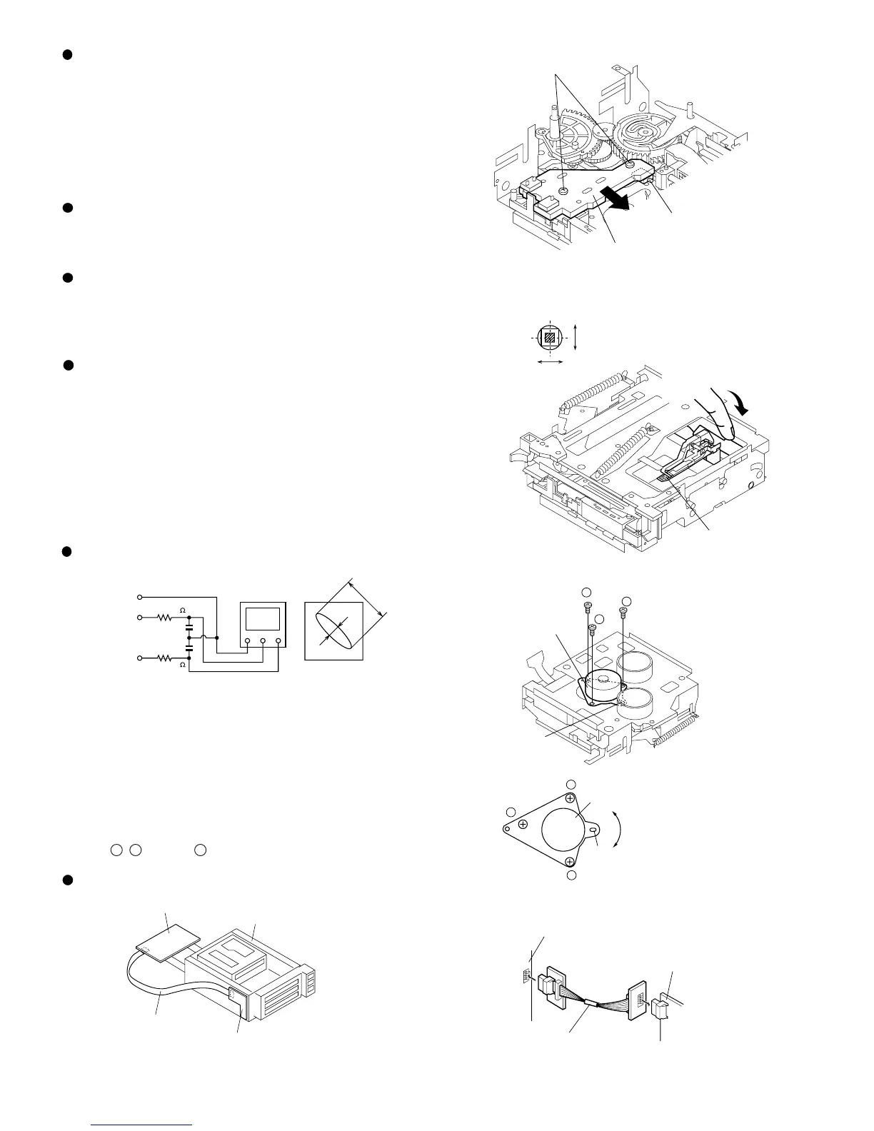
Figure 24-3 Optical Pickup Grating Deviation
Measuring Method
Mechanism Adjustment
1. Optical pickup grating inspecting method
After the automatic adjustment has been performed in the AUTO
mode (test mode) using the low reflection test disk MMD212 (TEAC)
("COMPLETE" will have been displayed), adjust the Lissajous
waveform (x-y) using EOUT and FOUT.
1. Slightly loosen the 3 screws of spindle motor, and make an
adjustment, observing the Lissajous's waveform.
2. After the adjustments are complete, tighten the screws in numerical
order:
1 , 2 and then 3 .
Lead-in switch position measurement mode
Insert High reflection test disk (TGYS1)
Note: Adjust the lead-in switch position to FF85 to FFDF.
1. Loosen the screw (A) x 2 pcs. which fix the mechanism switch
PWB.
2. Retighten the screw, pressing the mechanism switch PWB in
the arrow direction, and then measure the lead-in switch
position again.
After position adjustment fix with the two screws (A). (See Fig. 24-1.)
Note: After tightening the two screws on the PWB apply Screw Lock.
Figure 24-1
Forced rotation of loading motor
When STOP or EJECT appears in the display and the MD RELEASE
key is pressed, it allows the loading motor to be forced to run (loading
and unloading operations).
Figure 24-2
Figure 24-4
GND CH1 CH2
XY
GND (TP1131)
43 Pin of IC1101
26 Pin of IC1101
25 Pin of IC1101
EOUT (TP1133)
FOUT (TP1132)
100K
OSILLOSCOPE
470p
470p
a
b
Less than a:b = 4:1
LISSAJOUS'S WAVEFORM
100K
Adjustment of magnetic head mounting position
When the magnetic head and optical pickup have been replaced, be
sure to adjust the mounting position.
For easier adjustment of mounting position move the optical pickup
to the center position, and then adjust the position.
1. Set the adjusting transparent disc 3.
2. Lower the magnetic head up-shift arm with your finger, and raise
the magnetic head.
3. Viewing the set from above, make an adjustment so that the
magnetic head aligns with the optical pickup objective lens.
4. Make sure that there is a clearance as shown in Figure 24-2 and
the magnetic head moves up and down smoothly.
Figure 24-5
MD Mechanism Switch PWB
Lead in Switch
Loosen the two screws(A)
Optical Head
Optical Head
Radial direction
Objective lens
Circumferential direction
Push
2
2
1
1
3
3
Spindle Motor
Spindle Motor
Adjusting hole
Adjusting
hole
Forced movement into the loading mechanism throttle
positions
When STOP or EJECT appears in the display and the CD1 PLAY -
CD3 PLAY keys are pressed, the MD throttle mechanism can move
to positions 1 - 3.
MD CHANGER
SWITCH PWB
MD MAIN PWB
MD CHANGER UNIT
EXTENTION CABLE
QCNWK0122AFZZ
MAIN PWB
EXTENTION CABLE
QCNWK0123AFZZ
DISPLAY PWB
Figure 24-6
Connection of extension cable