EasyManua.ls Logo

Sharp PRO-60X5FD User Manual

Sharp PRO-60X5FD
88 pages
To Next Page IconTo Next Page
Page #1 background imageLoading...
Page #1 background image
Parts marked with " " are important for maintaining the safety of the set. Be sure to replace these parts with specified ones for maintaining the
safety and performance of the set.
SERVICE MANUAL
This document has been published to be used for
after sales service only.
The contents are subject to change without notice.
SAFETY PRECAUTION
IMPORTANT SERVICE SAFETY
PRECAUTION.....................................................i
PRECAUTIONS A PRENDRE LORS DE
LA REPARATION ...............................................ii
PRECAUTIONS FOR USING LEAD-FREE
SOLDER ........................................................... iii
OUTLINE
MAJOR SERVICE PARTS ................................iv
CHAPTER 1. SPECIFICATIONS
[1] SPECIFICATIONS ......................................... 1-1
CHAPTER 2. OPERATION MANUAL
[1] Parts Name .................................................... 2-1
[2] OPERATION MANUAL .................................. 2-3
CHAPTER 3. DIMENSIONS
[1] DIMENSIONS (PRO-60X5FD)....................... 3-1
[2] DIMENSIONS (PRO-70X5FD)....................... 3-2
CHAPTER 4. REMOVING OF MAJOR PARTS
[1] REMOVING OF MAJOR PARTS
(PRO-60X5FD)............................................... 4-1
[2] REMOVING OF MAJOR PARTS
(PRO-70X5FD)............................................... 4-6
[3] The location putting on the heat measure
sheet ............................................................ 4-11
[4] Precautions for assembly............................. 4-12
[5] The way of detaching Rear Cabinet
Ass'y............................................................. 4-14
CHAPTER 5. ADJUSTMENT
[1] ADJUSTMENT PROCEDURE ......................5-1
[2] PUBLIC MODE SETTING
PROCEDURE..............................................5-16
CHAPTER 6. TROUBLESHOOTING TABLE
[1] Failure diagnosis by LED in front of
cabinet ...........................................................6-1
[2] LED flashing specification at the time of an
error (Power LED used).................................6-1
[3] TROUBLESHOOTING TABLE ......................6-5
CHAPTER 7. MAJOR IC INFORMATIONS
[1] MAJOR IC INFORMATIONS .........................7-1
CHAPTER 8. OVERALL WIRING/SYSTEM BLOCK
DIAGRAM
[1] OVERALL WIRING DIAGRAM
(PRO-60X5FD) ..............................................8-1
[2] OVERALL WIRING DIAGRAM
(PRO-70X5FD) ..............................................8-2
[3] SYSTEM BLOCK DIAGRAM.........................8-3
Parts Guide
TopPage
CONTENTS
No. S81S7PR60X5FD
LCD COLOR TELEVISION
PRO-60X5FD
PRO-70X5FD
MODELS
In the interests of user-safety (Required by safety regulations in some countries) the set should be restored to its orig-
inal condition and only parts identical to those specified should be used.
PRO-60/70X5FD

Other manuals for Sharp PRO-60X5FD

Question and Answer IconNeed help?

Do you have a question about the Sharp PRO-60X5FD and is the answer not in the manual?

Sharp PRO-60X5FD Specifications

General IconGeneral
BrandSharp
ModelPRO-60X5FD
CategoryLCD TV
LanguageEnglish

Summary

Safety Precautions

Important Service Safety Precaution

Guidelines for qualified service technicians performing service checks.

Outline

Chapter 1. Specifications

Specifications

Technical specifications for the TV, including panel, receiving, terminals, OSD, power, weight, dimensions.

Chapter 3. Dimensions

Chapter 4. Removing of Major Parts

Chapter 5. Adjustment

Adjustment Procedure

Procedures for adjusting the unit after part replacement or software upgrade.

Upgrading of each microprocessor software

Instructions for upgrading microprocessor software using USB memory.

How to upgrade the software

Detailed steps for performing software version upgrade.

Monitor microprocessor software version upgrade

Procedure for upgrading the monitor microprocessor software.

Entering and exiting the adjustment process mode

Steps to enter and exit the adjustment process mode.

Remote controller key operation and description of display in adjustment process mode

Explanation of remote controller keys and display elements during adjustment.

List of adjustment process mode menu

Detailed list of adjustment items and their descriptions.

Writing the microprocessor software

Instructions for writing microprocessor software to the main PWB.

Signal adjustment

Procedures for signal adjustments related to the LCD section.

Image adjustment

Procedures for adjusting image parameters.

White balance adjustment

Procedures for white balance adjustment using a specific specification.

Factory setting

Procedure for configuring factory settings.

Chapter 6. Troubleshooting Table

Failure diagnosis by LED in front of cabinet

Flowchart for diagnosing failures based on the front LED status.

LED flashing specification at the time of an error (Power LED used)

Details on LED flashing patterns for error conditions and version upgrades.

LED flashing timing chart at the time of an error

Detailed timing charts for LED flashing patterns during various errors.

LED Backlight does not turn on.

Troubleshooting flowchart for scenarios where the LED backlight does not turn on.

Trouble Shooting Panel Module

Troubleshooting steps for panel module issues after replacing parts.

Picture does not display.

Troubleshooting flowchart for no picture display on composite inputs.

Component: No external input video [INPUT-6]

Troubleshooting flowchart for no video on component input.

No video at UHF/VHF broadcast signal reception.

Troubleshooting flowchart for no video on UHF/VHF broadcast reception.

No video at digital broadcast signal reception.

Troubleshooting flowchart for no video on digital broadcast reception.

PC: No external input video [INPUT-9]

Troubleshooting flowchart for no video on PC input.

<HDMI input> No video (5)-1

Troubleshooting flowchart for no video on HDMI INPUT-1.

<HDMI input> No video (5)-2

Troubleshooting flowchart for no video on HDMI INPUT-2.

<HDMI input> No video (5)-3

Troubleshooting flowchart for no video on HDMI INPUT-3.

<HDMI input> No video (5)-4

Troubleshooting flowchart for no video on HDMI INPUT-4.

<HDMI input> No video (5)-5

Troubleshooting flowchart for no video on HDMI INPUT-5.

Does not sound.

Troubleshooting flowchart for no audio on INPUT-7, INPUT-8, INPUT-6.

[PC analog audio input] INPUT-9 No audio.

Troubleshooting flowchart for no audio on PC analog input.

[HDMI analog audio input] INPUT-2 No audio.

Troubleshooting flowchart for no audio on HDMI analog input.

No audio at UHF/VHF broadcast signal reception.

Troubleshooting flowchart for no audio on UHF/VHF broadcast reception.

No audio at digital broadcast signal reception.

Troubleshooting flowchart for no audio on digital broadcast reception.

[INPUT-1 input]

Troubleshooting flowchart for no audio on HDMI INPUT-1.

No audio signal at Digital Audio Output terminal (Analog sound heard)

Troubleshooting flowchart for no audio at digital audio output terminal.

No monitor audio output

Troubleshooting flowchart for no audio output from the monitor.
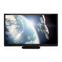
Chapter 7. Major IC Informations

Chapter 8. Overall Wiring/System Block Diagram

Printed Wiring Board Assemblies (PRO-60X5FD)

Cabinet Parts (PRO-60X5FD)

Related product manuals