I
f
L
LR2
3.SK,30
“R4J
R
2b
2
OK
RI9
e
T
27K
1
.
.
.
/.
Vi?33
I
I
:NP106
R21
2.7
K
P6
05
04
123
19K
-
47:;
R7
470K
Q7
0
D2
Dl
DAP401
DAP401
RI6
IK
RI6
1.3
K
t.
RI2
RII
RIO
3K
3K
3K
Mb-
R22
560
QI
-
Q3 A695
Q4m
Q7
C2320
Q8
A
798
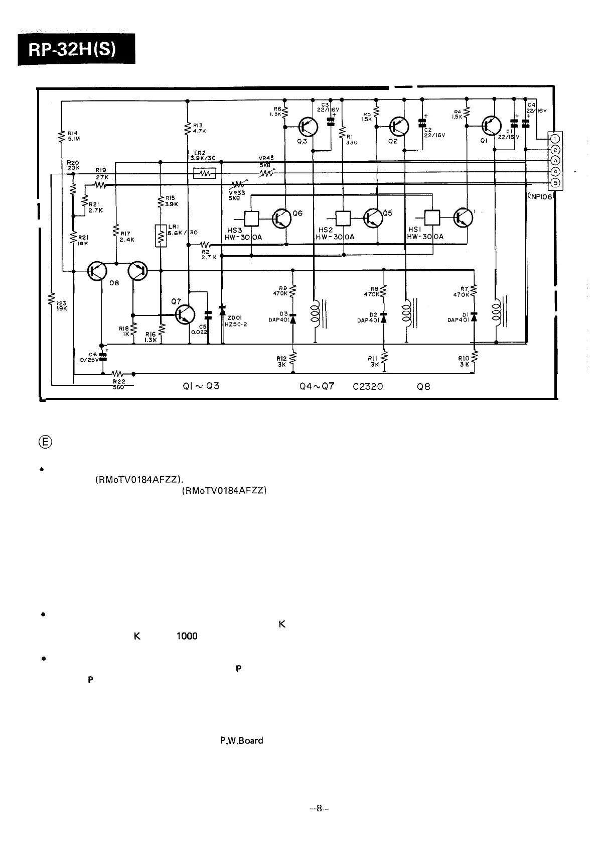
Figure8 TYPICAL SCHEMATIC DIAGRAM OF THE MOTOR
0
CAUTIONS
b
This schematic diagram refers to that of a typical unit of
the motor (RMoTV0184AFZZ).
l
Individual units of the motor (RMoTV0184AFZZ) are a
little different in their performance from one to another,
and the resistors and capacitors included in each unit are
different from those included in another.
It is therefore recommended not to repair the motor if it
gets in trouble. In such case, replace it with the new one.
NOTES ON SCHEMATIC DIAGRAM
0
Resistor:
To differentiate the units of resistors, such symbol as
K
is
used: the symbol
K
means
1000
ohm and the resistor
without any symbol is ohm-type resistor.
0
Capacitor:
To indicate the unit of capacitor, a symbol
P
is used: this
symbol
P
means micro-micro-farad and the unit of the
capacitor without such a symbol is microfarad. As to elec-
trolytic capacitor, the expression “capacitance/with-stand
voltage” is used.
l
Schematic diagram and Wiring Side of
P.W.Board
for this
model are subject to change for improvement without prior
notice.
-8-