29
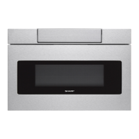
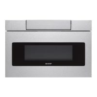
SMD2499FS
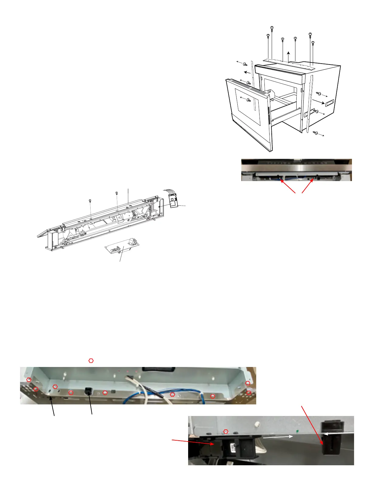
Fig. 2
1. Remove the (6) screws from the right & left Side Angles.
2. Remove the (7) C/P Cover screws behind the Control
panel (Fig 3)
3. Open the Cavity door
4. Remove (2) C/P screws from the black C/P Bracket under
the C/P Cover (Fig 4).
5. Lift the Control Panel Assy up and pull away from the cavity.
6. Open the hidden C/P and unplug all molexes except for
the IOT PWB (just take out the PWB along with the wire).
Fig. 3
CONTROL PANEL (C/P) REMOVAL
CPU REMOVAL
1. Lay C/P on a protected surface upside down and remove
the (2) screws using the access holes in the C/P bracket
(Fig 5).
2. Carefully lift off the CPU
3. Use reverse order to reinstall CPU and/or C/P
Fig. 5
PUSH LATCH & MOTION SENSOR ASSY REMOVAL
1. Follow C/P removal procedures.
2. Slightly open door.
3. Remove (8) screws holding the C/P Rear Cover to cavity (Fig 6).
4. Move both right & left chassis supports out and turn C/P rear cover upside down to have access to both Push
Latch & Sensor Assy.
5. Squeeze each bottom side of push latch to remove and remove (1) screw holding Sensor Assy (Fig 7).
6. Use reverse order to reinstall.
Fig. 6
Fig. 7
Screws
Push Latch
Sensor Assy
Bottom of
Push Latch
Sensor Assy
CPU
HIDDEN CONTROL PANEL
WIRELESS ADAPTER PWB
C/P Bracket
Screws (2)
Fig. 4