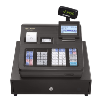
3) CKDC9 (HD404728B02FS)
3)-1. General description
The CKDC9 is a 4-bit microcomputer developed for the UP-600 and
provides functions to control the real-time clock, keys, and displays.
The basic functions of the CKDC7 are shown below.
Keys: The CKDC9 is capable of controlling a maximum of 256
momentary keys. (Sharp 2-key rollover control)
Simultaneous scanning of key and switch
(When a key is scanned, the state of a mode and clerk
switch is also buffered. The host can scan the state of
switch together with the key entry data at the same time
the key is scanned.)
Switches: Mode switch with 14 positions maximum
8-bit clerk (cashier) switch
2-bit feed switch
1-bit receipt on/off switch
1-bit option switch
4-bit general-purpose switch (1-bit is used for keyboard
select)
Displays: 16-column dot display
12-column 7-segment display (column digit selectable)
All column blink controlled for the dot and 7-segment dis-
play decimal point and indicators
Programmable patterns for 7-segment display:
Four patterns
Internal driver for 7-segment display
Buzzer: Single tone control
Clock: Year, month, day of month, day of week, hour, minute
Alarm: Hour, minute
Interrupt request (event control):
Detection of key input, switch position change, alarm is-
sue, and counter overflow
3)-2. Pin description
Pin
No.
Symbol
Signal
name
In/
Out
Function
1 SB SB Out Segment B
2 SC SC Out Segment C
3 SD SD Out Segment D
4 SE SE Out Segment E
5 SF SF Out Segment F
6 SG SG Out Segment G
7 P4 AP Out
8P0 NC—NC
9P1 NC—NC
10 P2 DP Out Decimal point
11 P3 ID Out Indicator
12
MODR VCC — +5V
13
CFSR CFSR In
Clerk key, Feed key, Switch
return signal
14 KEX0 NC Out NC
15 KEX1 NC Out NC
16 RQ GND — GND
17 SKR0 VCC — +5V
18 ST0 ST0 Out Key strobe signal
19 ST1 ST1 Out Key strobe signal
20 ST2 ST2 Out Key strobe signal
21 ST3 ST3 Out Key strobe signal
22
POFF POFF In Power off signal
23
STOP STOP In STOP signal
24
DDIG VCC — +5V
Pin
No.
Symbol
Signal
name
In/
Out
Function
25
DCS DCS —
Dot display controller chip select
DCS
26 VCC
VCKDC — +5V
27
SCK SCK In Clock signal
28 HTS HTS In Key data from host
29 STH STH Out Key data to host
30 SDISP GND — GND
31 BUZZ BUZZ Out Buzzer
32
DSCK DSCK — Dot display controller SCK
33
SRES RESET Out Reset signal
34 DS0
DSO — Dot display controller SO
35
SHEN SHEN Out Shift enable signal
36
IRQ KRQ Out Key request signal
37 KR0
KR0 In Key return signal
38 KR1
KR1 In Key return signal
39 KR2
KR2 In Key return signal
40 KR3
KR3 In Key return signal
41 RESET CKDCR In CKDC reset signal
42 OSC2 OSC2 — Clock
43 OSC1 OSC1 — Clock
44 GND GND — GND
45 CL1 CL1 — Time clock
46 CL2 CL2 — Time clock
47 TEST VCKDC — +5V
48 G0 G1 Out Display digit signal
49 G1 G2 Out Display digit signal
50 G2 G3 Out Display digit signal
51 G3 G4 Out Display digit signal
52 G4 G5 Out Display digit signal
53 G5 G6 Out Display digit signal
54 G6 G7 Out Display digit signal
55 G7 G8 Out Display digit signal
56 G8 G9 Out Display digit signal
57 G9 G10 Out Display digit signal
58 G10 G11 Out Display digit signal
59 G11 NC Out NC
60 PO0 NC NC
61 PO1 NC NC
62 PO2 NC — NC
63 PO3 NC — NC
64 SA SA — Segment A
4) LCD CONTROLLER (M66271FB)
4)-1. Pin configration
9
78
66
67
69
70
71
72
68
11
7
6
5
4
3
2
31
30
29
28
27
26
22
21
20
19
18
17
16
15
62
61
14
60
59
58
57
56
55
54
53
50
49
48
47
46
45
44
43
77
63
52
42
34
23
8
12
79
76
74
73
75
32
39
38
37
36
33
51
80
65
1
40
35
24
13
25
64
41
10
A13
A12
A11
A10
A9
A8
A7
A6
A5
A4
A3
A2
A1
A0
M
LCDENB
MPUCLK
OSC1
CP
LP
UD0
UD1
UD2
UD3
FLM
RESET
WAIT
MCS
RD
LWR
HWR
IOCS
MPUSEL
OSC2
N.C
N.C
N.C
N.C
N.C
N.C
N.C
N.C
N.C
N.C
VSS
VSS
VSS
VSS
VSS
VSS
VSS
VSS
VSS
VSS
VSS
VSS
BHE
D15
D14
D13
D12
D11
D10
D9
D8
D7
D6
D5
D4
D3
D2
D1
D0
VDD
VDD
VDD
VDD
VDD
VDD
VDD