‐2‐
2-3. Installation Conditions (environmental conditions)
Note:
This instrument should not be used in any of the places mentioned
below. Selection of any of the places may result in trouble with the
instrument, damage to it or even a fire.
Where flammable gas, corrosive gas, oil mist and particles
that
can deteriorate electrical insulation are generated or abundant.
Where the temperature is below -10°C or above 50°C.
Where the relative humidity is above 90% RH or below the
dew point.
Where highly intense vibration or impact is generated or
transferred.
Where the instrument is exposed to dew drops or direct sunlight.
Where th
e instrument is directly exposed to the air of the heater
or the air conditioner.
Where the height is above 2000
m.
Outdoors
2-4. Site selection (environmental condition
s)
This instrum
ent is specified to be used in the following
environment
conditions.
Indoor use
Altitude up to 2000m
Transient overvoltage category II
POLLUTION DEGREE 2 in accordance with
IEC60664
2-5.
Mounting
Cut a hole for mounting the controller in the panel by referr
ing
to th
e cutout drawing in section
2-5.
The p
anel thickn
ess should be 1.0-4.0mm.
As the instrum
ent is provided with pawls for fixi
ng, just press it
firmly
from the front of the pane
l.
Please mount v
ertically in order to satisfy the dust-proof/drip-
proof (NEMA4X, IP66) specification.
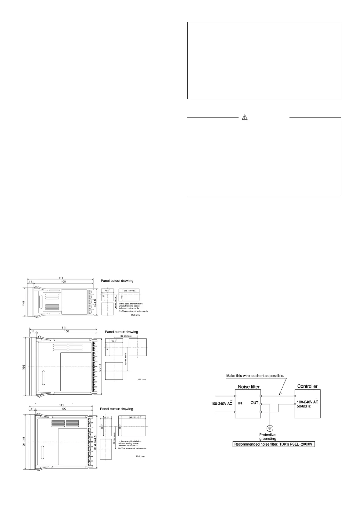
2-6. External Dimensions and Panel Cuto
ut
SR1(48×48mmsize)
SR3(96×96mmsize)
SR4 (96×48mm size)
Minimum distance is 20mm when plural instrum
ents are installed side
by side.
Note 1: W
hen installing without leaving space between
instruments, dust-proof/drip-proof, (NEMA4X, IP66)
specification would not be satisfied.
Note 2: Extracting the internal portion of the instrument
For safety's sake and to protect the functionality of the
product, do not draw out the body from its case. IEC
61010-1 safety standards request for the use of tools this
instrument from the case. This is designed to prevent
electric shock.
Recommended tools (minus driver, shape of the tip:
width 4.5mm, thickness 0.5mm)
3. Wiring
WARNING
This product is double-insulated. Input terminals
(
Current/Voltage, Themocouple, R.T.D.) or Output termin
als
(Voltage/Current, SSR) must not which are neither double-
insulated nor reinforced-insulated from connect to SELV
circuits, MAINS circuits.
Fil
ure to do so could result in electric sh
ock.
Mak
e sure to disconnect this product from any power sour
ce
du
ring the wiring operation. Otherwise an electric shock may
result.
T
o prevent an electric shock, do not touch wired terminals
and
othe
r charged elements while they are being energized.
3-1. Note on Wiring
In the wiring operation, follow the terminal layout shown in
section 3-2 and make sure to carry out the correct wiring process.
Use a press fit terminal which fits an M3.5 screw and has a width
of 7mm or less.
In case of thermocouple input, use a compensating wire
compatible with the selected type of thermocouple.
In case of R.T.D. input, the resistance of a single lead wire must
be 5Ω or less and the three wires must have the same resistance.
When the current input is 0–20mA (0–5 DC),
4–20mA
(1–
5V DC), select input [6] (see 1-22) and apply
supplied
shunt
resistor of 250Ω ±0.1% between the input
terminals + and – for the use of instrument.
The input signal wire must not be accommodated with a high
voltage power cable in the same conduit or duct.
Shield wiring (single point grounding) is effective against static
induction noise.
Twisting the input wires at short and equal intervals is effective
against electromagnetic induction noise.
Clamp the screws of terminals firmly.
Clamping torque: 1.0 N
·
m (10 kgf
·
cm)
If the instrument appears to be easily affected by power supply
noise, use a noise filter to prevent malfunctioning. Mount the
noise filter on the grounded panel and make the wire connection
between the noise filter output and the power line terminals of
the controller as short as possible.
 Loading...

