‐1‐
This product is manufactured as built-in equipment. Be sure to
mount on a panel or an enclosure.
Installation must be done by qualified personnel.
Do not use this product where explosive gas exists.
Safety Rules
For matters regarding safety, potential damage to equipment and/or
facilities, additional instructions and notes are indicated by the
following headings.
WARNING
This heading indicates hazardous conditions that could cause injury
or death of personnel unless extreme caution is exercised.
CAUTION
This heading indicates hazardous conditions that could cause
damage to equipment and/or facilities unless extreme caution is
exercised.
NOTE
This heading indicates additional instructions and/or notes.
WARNING
The SR1, 3, 4 series digital controllers are control instruments
designed for industrial use to control temperature, humidity and
other physical values. Avoid using it for control of devices upon
which human life is dependant. When used, adequate and
effective safety measures must be taken. No warranty is valid in
the case of an accident arising from the use of this product
without having taken such safety measures.
Be sure to turn off power while performing wiring. Failure to
do so could result in electric shock. After wiring, do not touch
terminal elements or other charged parts. Failure to do so could
result in electric shock.
Never remove the controller from its case. Doing so could
result in electric shock.
CAUTION
Be sure to follow the instruction manual when operating this
device. If the SR1,3,4 series is used in a manner not specified
in this manual, the protection provided by the SR1,3,4 series
may be impaired.
Do not use this instrument other than specified.
Using the instrument other than specified may result in trouble
with the instrument or may cause a fire.
Voltage/current of a load to be connected to the output terminal
should be within a rated range.
Do not blo
ck the draft hole or allow dust and the like to stick to
the case of the instrument for heat discharge.
A rise in temperature or insulation failure may result in a
reduction of the life of the product and/or problems with it or
may cause a fire.
Do not operate keys on the front panel with a hard or sharply
pointed object. Operate the keys only by softly touching them
by your fingertips.
When cleaning the instrument, wipe it gently with a dry cloth.
Never use solvent such as thinner.
It takes 30 minutes to display the correct temperature after
applying power to the digital controller. (Therefore, turn the
power on more than 30 minutes prior to the operation.)
1. Introduction
1-1. Check before Use and Confirmation of Model Codes
This product has been fully inspected for quality assurance prior to
shipment. However, you are requested to make sure that there is
no error, damage or shortage of delivered items by checking the
model codes and the external view of the product.
Confirmation of Model Codes
Check the
model codes affixed to the case of the product to
ascertain if the respective codes designate what was specified
when you ordered it, referring to the following code table.
Series code SR1: 48×48mm DIN
SR3: 96×96mm DIN
SR4: 96×48mm DIN
Input
[8] The
rmocouple, R.T.D., mV Voltage, Multi-
input
[6] Voltage: -1
-1, 0-1, 0-2, 0-5, 1-5,0-10V DC
* Will correspond to external moun
ting
resistance of (25
0) for current input.
Control output
[Y] Contact, [I] Current,
[P] SSR drive voltage, [V] Voltage
Event
[0] 1ax1
[1] 1a×2
Remarks [0] Without (Case: Black)
[9] With (Case: B
lack)
[W] Without (Cas
e: Ivory)
[X] With (Case: I
vory)
[1-8,A,B,D-V,
Y]
Customized
firmware
Product information(3 characters)
1st character [A] Conformed to UL 610101-1 3rd Edition
2nd, 3rd character other than [00] Conformity to other standards.
2. About Installation
2-1. Installation
This instrument is created with the premise of being used by
setting on the instrumentation panel. Therefore, please make
sure that the user would not come in contact with the live part of
the power terminals and the like.
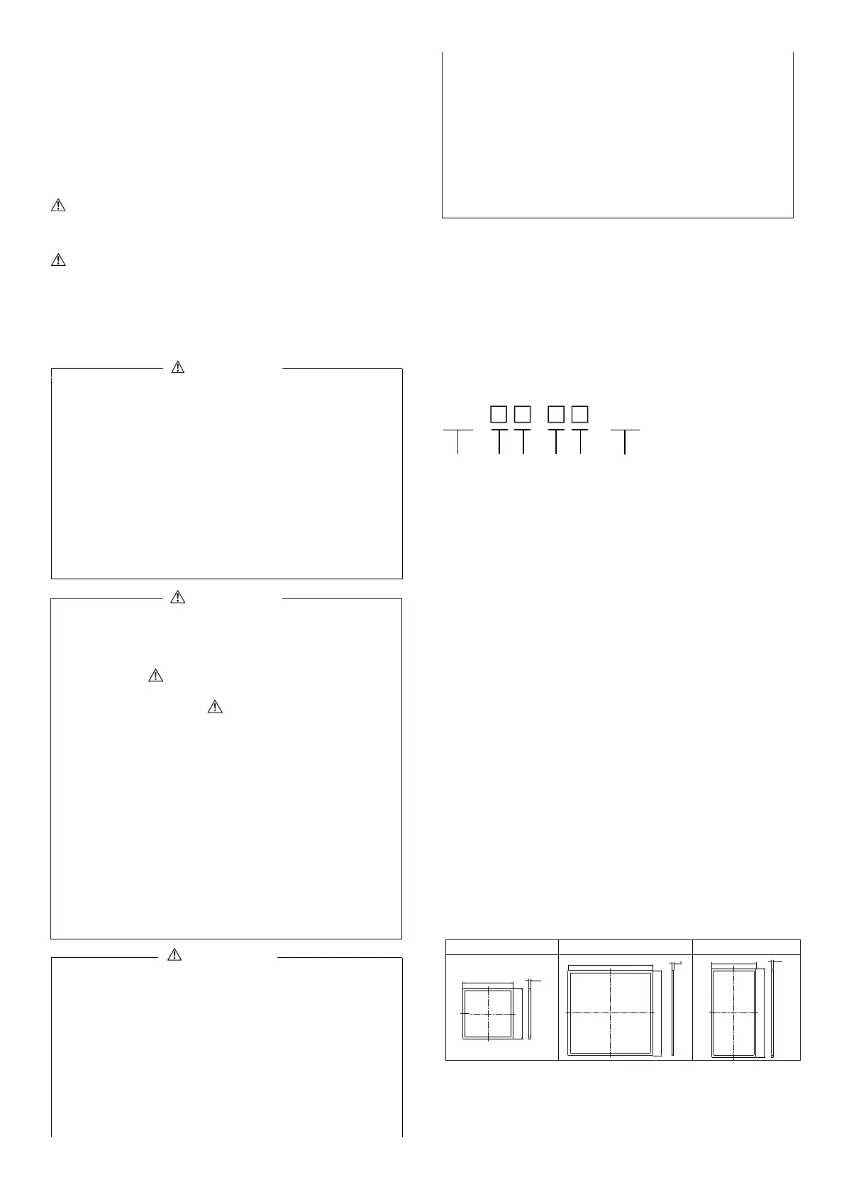
2-2. replacement Part
Be sure to install this product with the attached gasket. Use a
genuine gasket for replacement. Part numbers are as follows.
SR1:QCG001 SR3:QCG003 SR4:QCG004
46.1
0
-0.5
46.1
0
-0.5
2
+0.2
0
92.5
0
-0.5
92.5
0
-0.5
2
+0.2
46.1
0
-0.5
92.1
0
-0.5
2
+0.2
0
CAUTION
To avoid damage to connected equipment, facilities or the SR1,
3, 4 itself due to a fault of the product, safety measures must be
taken before usage, such as the installation of a fuse, an
overheating protection device and the like.
The alert mark on the plate affixed to the instrument:
On the terminal nameplate affixed to the case of this
instrument, the alert mark is printed. This is to warn you
of the risk of electric shock which may result if the charger is
touched while being energized.
As a means to turn the power off, a switch or a breaker should
be installed in the external power circuit to be connected to the
power terminal of the instrument.
As a means to turn the power off, a switch or a breaker (which
confirms with IEC 60947) should be installed in the external
power circuit to be connected to the power terminal of the
instrument.
Since the instrument does not have a built-in fuse, do not forget
to install a fuse in the power circuit to be connected to the
power terminal.
Fuse rating/characteristics: 250V AC 0.5A/medium lagged or
lagged type.
Use a fuse which conforms with IEC 60127.
SR1 - -
A00
① ② ③ ④ ⑤ ⑥
 Loading...

