‐3‐
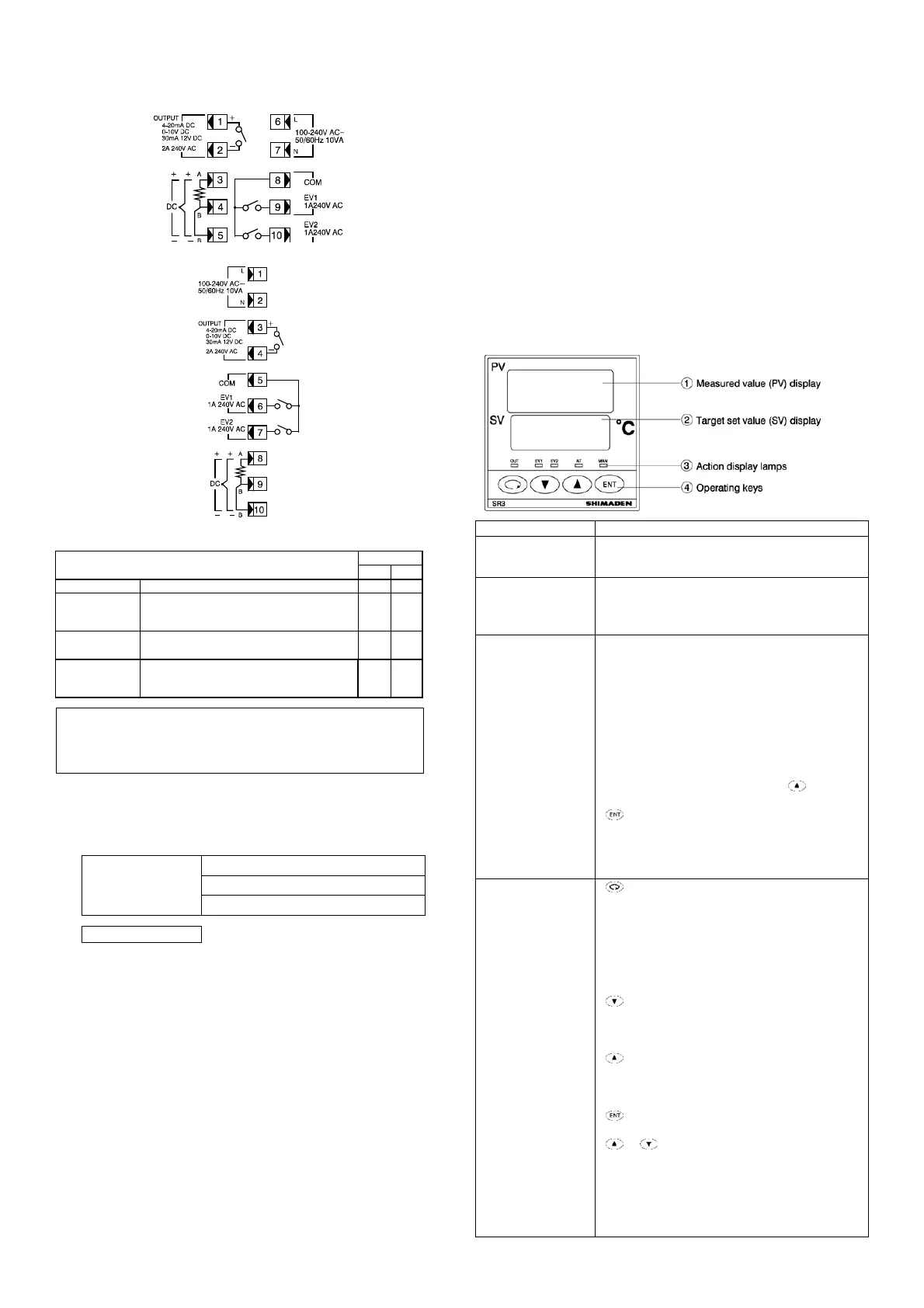
3-2. Terminal Layout
SR1
SR3/SR4
3.3 Terminal Arrangement Table
Name of
terminal
Terminal
No.
SR1 SR3/4
Power
terminal
100-240V AC±10% 50/60Hz
10VA
6-7 1-2
Input
signal
R.T.D.: A, thermocouple/voltage: +
R.T.D.: B
R.T.D.: B, thermocouple/voltage: −
3
4
5
8
9
10
Output
terminal
Contact: COM, SSR drive voltage/voltage/current: +
Contact: NO, SSR drive voltage/voltage/current: −
1
2
3
4
Event
output
terminal
COM: Common terminal
EV1: Event 1 output terminal (standard)
EV2: Event 2 output terminal (standard)
8
9
10
5
6
7
Note: Shorting across B and B terminal will cause an error
when thermocouple/voltage/current is inputted.
If used with input current, apply supplied shunt resistor
of 250 ±0.1% between input terminals (+,−).
3-4. Insulation Block
The layout of the insulation block is as follows.
In the below table,
a circuit which is divided by lines is the circui
t
which is insulated from other circuits
Power supply
Input
Output
Event output
Reinforced insulation
4. Outline of Specifications
Display
Display accuracy
Display accuracy maintaining
range
Measured value display range
Setting
Setting method
Setting limiter
Input
PV bias
PV filter
Maximum rated voltage
Maximum rated current
Control
Control mode
Type of control output
Output control characteristics
± (0.3% FS+1digits)
23±5°C
Input r
ange or 10–110% of measuring range
By operating 4 keys on the front panel Within
the measuring range, individual setting for
higher and lower limits
(Lower limit<Higher limit)
1999–2000 digits
0–100 seconds
10V DC
24mA DC
Auto tuning PID control, manual control
Relay contact, SSR drive voltage, voltage,
current
RA/DA switching
Output limiter Lower limit: 0.0 - 99.9%
Upper limit: lower limit +0.1-100.0%
Event
Output points 2 points EV1, EV2
Contact rating 240V AC 1A (resistive load)
Event type Absolute values, deviations (higher, lower,
higher/lower, within, outside)
Event action On-Off action
Standby action Selectable from the 3-type standby mode
General specifications
Operational condition
Ambient temperature -10 to +50°C
Ambient humidity Below 90%RH
(no dew condensation)
Supply voltage 100 to 240V AC±10% 50/60Hz
Power consumption
Protective structure
Material of case
Approximately 10VA
Only front panel has dust-proof and drip-
Proof structure equivalent to IP66.
(Panel thickness:1.2 to 32.mm)
PPE resin molding
(equivalent to UL94V-1)
5. Names and Functions of Parts on Front Panel
Name Function
Measured value
display
• Displays measured value (PV) or each type of
parameter signs (red)
Target set value
display
• Displays target set value (SV), each type of
parameter set value
• Output value is displayed by % on control output
monitor screens of the screen group 0 (green)
Action display
• Out (green) /Control output display
• Lights when output turns on during contact or
SSR
dr
ive voltage output.
• Turns off when output is 0% during voltage or
current and flashes continuously
when output is
100%.
• Flashes on a equal basis of 0.5 sec for others.
• EV1, EV2 (orange)/ Ev
ent output display
• L
ights during event output.
• AT (green)/ auto tuning action display
• Flashes when ON key is selected by key on the
AT action selection screen and AT is executed by
key and goes out when AT terminates
automatically or is released.
• MAN (green) /Manual control action display
• Flashes when manual control action mode is
selected.
Operating keys
• Parameter key
• Pressing this key on any screen of the screen
group 0 and the screen group 1 calls the next
screen onto display.
• When pressed continuously for 3 seconds, this
key functions to move toward the basic screen of
screen group 0 and the initial screen of screen
group 1.
• Down key
• When pressed on each of the screen, the decimal
point of the rightmost digit flashes and the set data
decreases or moves backward.
•
Up key
• When pressed on each of
the screen, the decimal
point of the rightmost digit flashes and the set data
increases or moves forward.
• Registration (entry) key
• Used to register a set data changed by means of
or key on a parameter screen. (The
flashing right most digit turns off.)
• When pressed continuously for 3 seconds on the
control output screens (mode 0 to 1), this key
functions to switch between the manual control
mode (Man flashes) and the automatic control
mode (Man turns off).
 Loading...

