‐7‐
7. Event Action
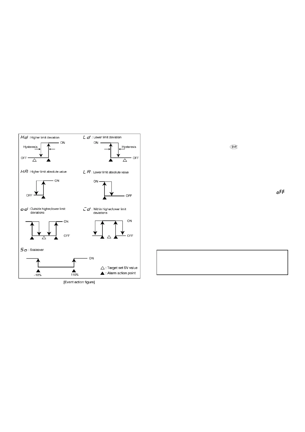
7-1. Deviation Alarm
The alarm action point will change along with the Target set value
(SV). For examp
le, when the target set value is 20°C, +10 should be
set for higher limit deviation alarm in order to put an alarm in action
at 30°C
and higher. To put an alarm action at 30°C and
lower when
the target set value is 100°C, −70°C should be set for higher limit
deviation alarm.
7-2. Absolute Value Alarm
An alarm action point is set by an absolute value. For example, when
the measur
ed value exceeds 100°C, 100°C should be set for higher
limit absolute alarm in order to put an alarm in action at 100°C and
higher. To
put an alarm in action at 70°C and lower 70°C should be
set for lower limit absolute alarm.
In case of absolute value alarm, the alarm only works for th
e
measured value (PV) with no relation to the target set value (SV).
7-3. Standby Action (Mode 1-13)
This is used to withhold alarm action even when an alarm action
point is reached when power is applied and to put the alarm in action
on the alarm action point after
a target set value (SV) is reached.
Selec
t an action code from the standby action code table when
event output is used as an alarm and standby becomes necessary.
Set and select code 4 when event output is used for control.
However, note that setting 4 will turn event output OFF if input
goes out of order.
When code 2 is selected, the standby function is put in action only
when power is applied.
When code 3 is selected, standby function is put in action when
power is applied and when SV in execution is changed.
When a standby code is changed while standby action is
in
execution, it may be possible for the standby action to be released.
No-standb
y action is where the alarm is output any time the
measured value (PV) reaches the alarm action point whether power
is applied or not.
7-4. Standby action code table
1: No standby action
2: Standby action only when power is applied
3: Standby action when power is applied or when changed to SV
4: Control mode
(no standby)
8. Before starting up
Before operation, check the wiring and set the items listed below by
the setting methods of the screen groups. However, for factory- set
items and items already set by equipment manufacturers,
preparation is unnecessary.
(1) Checking of Wiring
Check that the wiring connected to the terminals is carried out
properly.
(2) Application of Operating Power
Apply operating power. The controller is energized and the data
display and other lamps light.
(3) Setting of Measuring range and input type
Select input type, code and register by
from the setting range
codes of Mode 1 screen (1-22) "Measuring range selection setting
screen." In the case of current and voltage input, the measuring range
of lower limit values, higher limit values opposed to input signals and
the position of decimal point will be set.
(4) Setting of control type
In the case of ON-OFF (two positions) action, call the mode 1
(1-2) "Proportio
nal band setting" screen and select and regi
ster
If used with PID auto tuning, setting can remain unchanged.
(5) Setting of Control Output Characteristics
Select either heating (RA) or cooling (DA) characteristics from
mode 1 (1-17) "Control output characteristics setting" screen.
(6) Setting of Event (EV1, EV2) Action Type
Select and register a code for either mode 1 (1-11, 1-13, 1-14, 1-16)
"Alarm code" or
"Alarm standby code".
Note: When input types, measuring range is
selected and
changed, all the set data concerning measuring range
will be initialized.
 Loading...

