5
2. Disassembling and Assembling the Balance
2.1. Precautions
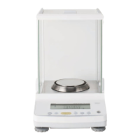
1) Pull the connector straight out when disconnecting. Never pull it out at a bent angle.
* Pulling out at a bent angle could bend the terminal pins, making it difficult to re-insert the
connector.
Fig. 2-1
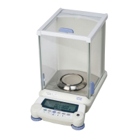
2) When assembling the base unit ASSY (2) and case ASSY (3), check that the power board ASSY (B4)
connector is firmly inserted.
* An insufficiently inserted connector could lead to instability in the display.
Fig. 2-2
3) When performing disassembly and assembly of the unit ASSY (1), insert the lever fixing pin (J1) into the
lever fixing hole on the top of the OPF.
* Lift up on the lever ASSY (1) to insert the pin. Proceed carefully to avoid scratching the elastic
support.
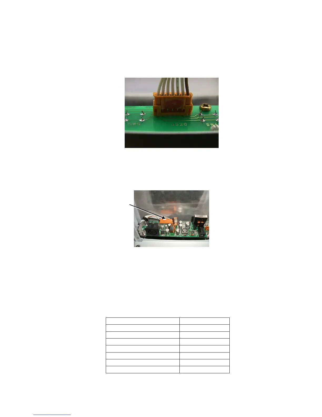
4) Use a controlled torque driver to tighten the screws to the torques shown in the table below.
 Loading...