15
Installation/removal
Wiring example
Installation/removal
Wiring example
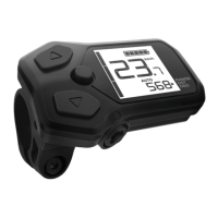
Satellite system ON/OFF
switch *1
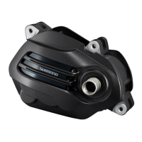
To terminal block of drive unit *2
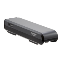
Battery
Battery mount
Power cord (to charging port of drive unit)
Satellite charging port *3
*1 There are two types of satellite system ON/OFF switches, one using EW-SD50 type electric
wire and the other using EW-SD300 type electric wire. (Refer to “Electric wires.”)
*2 Connect the electric wire of the satellite system ON/OFF switch to the terminal block of the
drive unit or to the drive unit via junction [B].
*3 Take care to ensure that the satellite charging port is compatible with the battery mount. For
details, refer to the compatibility information at https://productinfo.shimano.com.
NOTICE
• The maximum electric wire length between components is 1,600 mm. Ensure that the
total length is 1,600 mm or less when connecting via a junction [B] or conversion
adapter.