4(29)
4.1.4 PID Setting ................................................................................. 23
4.1.5 Intermittent Operation Setting ..................................................... 24
4.1.6 One-week Timing Setting ........................................................... 24
4.1.7 Communication Setting (optional functions) ............................... 24
4.1.8 Operation Flow ........................................................................... 26
4.1.9 Wrong Codes Remark ................................................................ 27
5. Maintenance and Repair ............................................................................... 28
5.1 Blower ................................................................................................... 28
6. Troubleshooting ............................................................................................ 29
Table Index
Table 1‑1:Dryer drying capacity(kg/hr)(Selection guide) .............................. 9
Table 1‑2:Label Description ........................................................................... 11
Table 2‑1:Configuration Table ........................................................................ 13
Table 2‑2:Configuration Table ........................................................................ 13
Table 2‑3:Configuration Table ........................................................................ 14
Table 2‑4:Configuration Table ........................................................................ 14
Table 4‑1:PID Setting Parameter ................................................................... 24
Table 4‑2:Communication Setting Parameter ................................................ 25
Table 4‑3:Error Code Description ................................................................... 27
Table 6‑1:Common Faults and Troubleshootings .......................................... 29
Picture Index
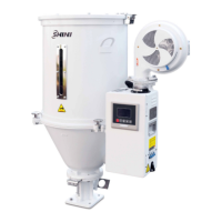
Picture 1‑1:SHD-50E ........................................................................................ 6
Picture 2‑1 Working principle ............................................................................ 12
Picture 3‑1:Direct Installation ......................................................................... 17
Picture 3‑2:Blower .......................................................................................... 19
Picture 3‑3:Left:Air-exhaust elbow of dryer Right:Air-exhaust filter ......... 19
Picture 3‑4:European suction box .................................................................. 20
Picture 3‑5:Shut-off suction box ..................................................................... 20
Picture 3‑6:Right:AIF blower inlet filter ......................................................... 20