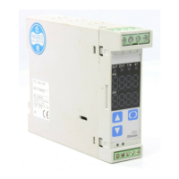
2. Name and functions of the sections
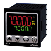
(1) EVT indicator
A red LED lights up when Event output [Alarm, Loop break alarm
or Heater burnout alarm (Option)] is ON.
(2) OUT indicator
A green LED lights up when OUT output is ON.
For current output type, this blinks in 0.25 seconds cycle
corresponding to the output manipulated variable .
(3) T/R indicator
A yellow LED blinks while serial communication TX output (Transmission)
(4) AT indicator
A yellow LED blinks while PID auto-tuning is being performed.
(5) PV display
Indicates input value (PV) with a Red LED.
(6) SV display
Indicates setting value (SV) with a Green LED.
(7) Increase key
Increases numeric value.
(8) Decrease key
Decreases numeric value.
(9) Mode key
Changes the setting mode or registers the setting value.
(Resisters the setting value by pressing the Mode key.)
(10) Sub-mode key
Calls auxiliary function setting mode 2 in combination with the mode key.
(Fig. 2-1)
Caution
When setting the specifications and functions of this controller, connect the terminals 1 and 2 for power
source first, then set them referring to “5. Setup” before performing “3. Mounting to the control panel”
and “4. Wiring”.
3. Mounting to the control panel
3.1 Site selection
This instrument is intended to be used under the following environmental conditions (IEC61010-1).
: Overvoltage category
, Pollution degree 2
Mount the controller in a place with:
• A minimum of dust, and an absence of corrosive gases
• No flammable, explosive gasses
• Few mechanical vibrations or shocks
• No exposure to direct sunlight, an ambient temperature of 0 to 50 (32 to 122 ) without rapid change
• An ambient non-condensing humidity of 35 to 85%RH
• No large capacity electromagnetic switches or cables through which large current is flowing
• No water, oil or chemicals or where the vapors of these substances can come into direct contact with
the controller
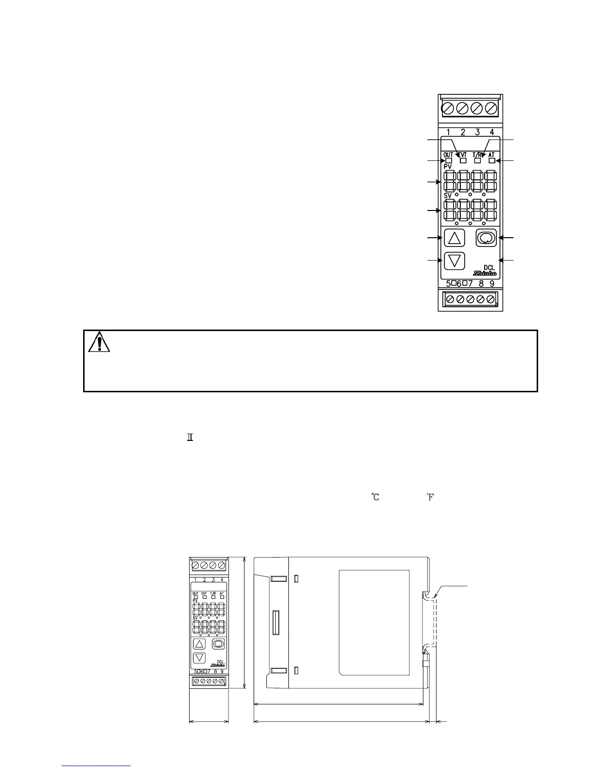
3.2 External dimension
(Fig. 3.2-1)
97
100
4
DIN rail
22.5
75
(1)
(2)
(5)
(6)
(3)
(4)
(7)
(8)
(9)
(10)
 Loading...