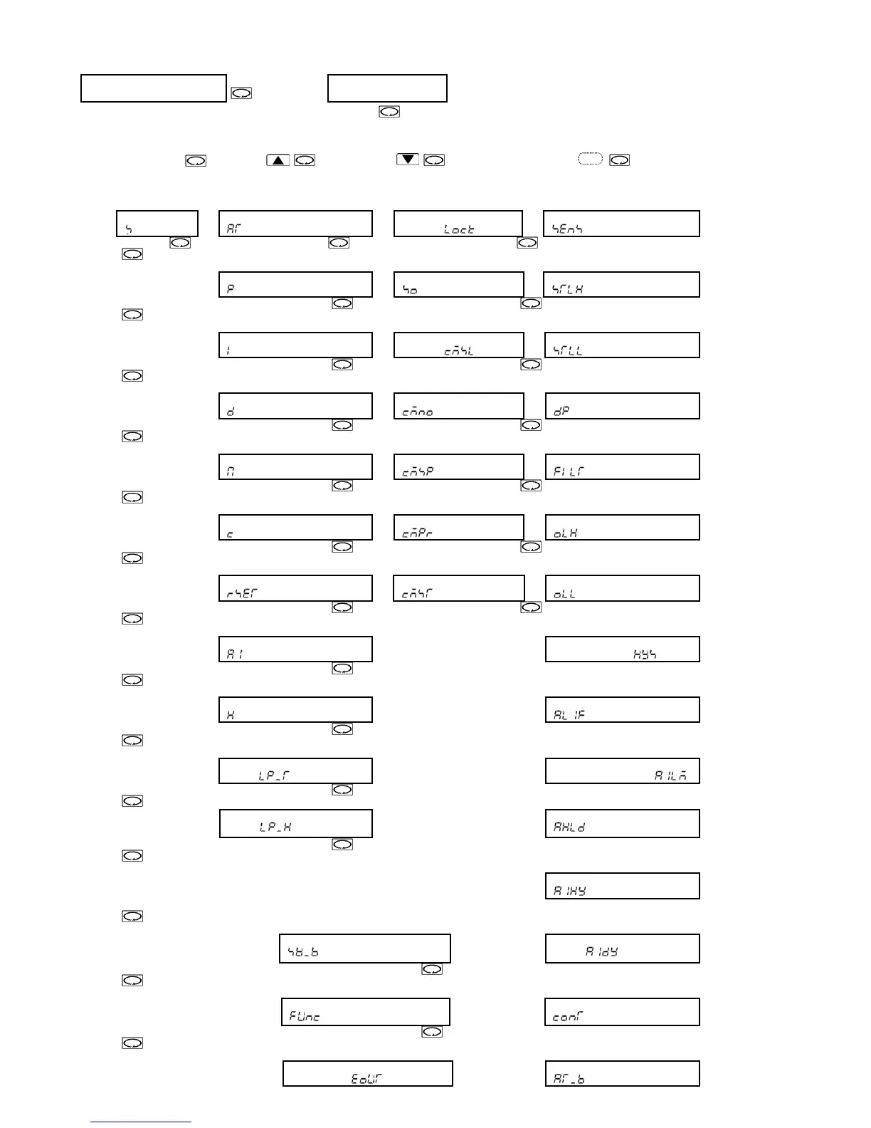
5.1 Setting flow chart
PV/SV display mode
(Approx. 3s)
Output manipulated
variable
+
+ (Approx. 3s)
+
(Approx. 3s)
[Main setting mode] [Sub setting mode] [Auxiliary function [Auxiliary function 2
setting mode 1] setting mode 2]
SV
[
]
AT setting
[ ]
Setting value LOCK
selection [ ]
Sensor selection
[ ]
OUT proportional band setting
[
]
Sensor correction setting
[ ]
Scaling high limit setting
[ ]
Integral time setting
[
]
Communication protocol
selection [ ]
Scaling low limit setting
[ ]
Derivative time setting
[
]
Instrument No. setting
[ ]
Decimal point place selection
[ ]
ARW setting
[
]
Data transfer rate selection
[ ]
PV filter time constant setting
[ ]
OUT proportional cycle setting
[
]
Parity selection
[ ]
OUT high limit setting
[ ]
Manual reset setting
[
]
Stop bit selection
[ ]
OUT low limit setting
[ ]
Alarm setting
[
]
OUT ON/OFF action
hysteresis setting [ ]
Heater burnout alarm setting
[
]
Alarm action selection
[ ]
Loop break alarm action time
setting [
]
Alarm action Energized/
Deenergized selection [ ]
Loop break alarm action span
setting [
]
Alarm HOLD function selection
[ ]
Alarm hysteresis setting
[
]
SVTC bias setting
[
]
Alarm action delayed timer
setting [ ]
Controller/Converter selection
[
]
Direct/Reverse action selection
[ ]
Output status selection when
input burnout [
]
AT bias setting
[ ]
(Approx. 3s)
 Loading...