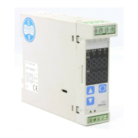
• Option: Heater burnout alarm
This alarm is not available for detecting current under
phase control.
Use the current transformer (CT) provided, and pass
a lead wire of the heater circuit into a hole of the CT.
When wiring, keep the CT wire away from any AC
source or load wires to avoid the external interference.
(Fig. 4-2)
5. Setup
The sensor input character and temperature unit are indicated on the PV display for approx. 3 seconds
after the power is turned on, and the input range high limit value is indicated on the SV display. (Table 5-1)
(If any other value is set in the scaling high limit value, it is indicated on the SV display.)
During this time all outputs and the LED indicators are in OFF status. After that the control
starts indicating actual temperature on the PV display and setting value on the SV display.
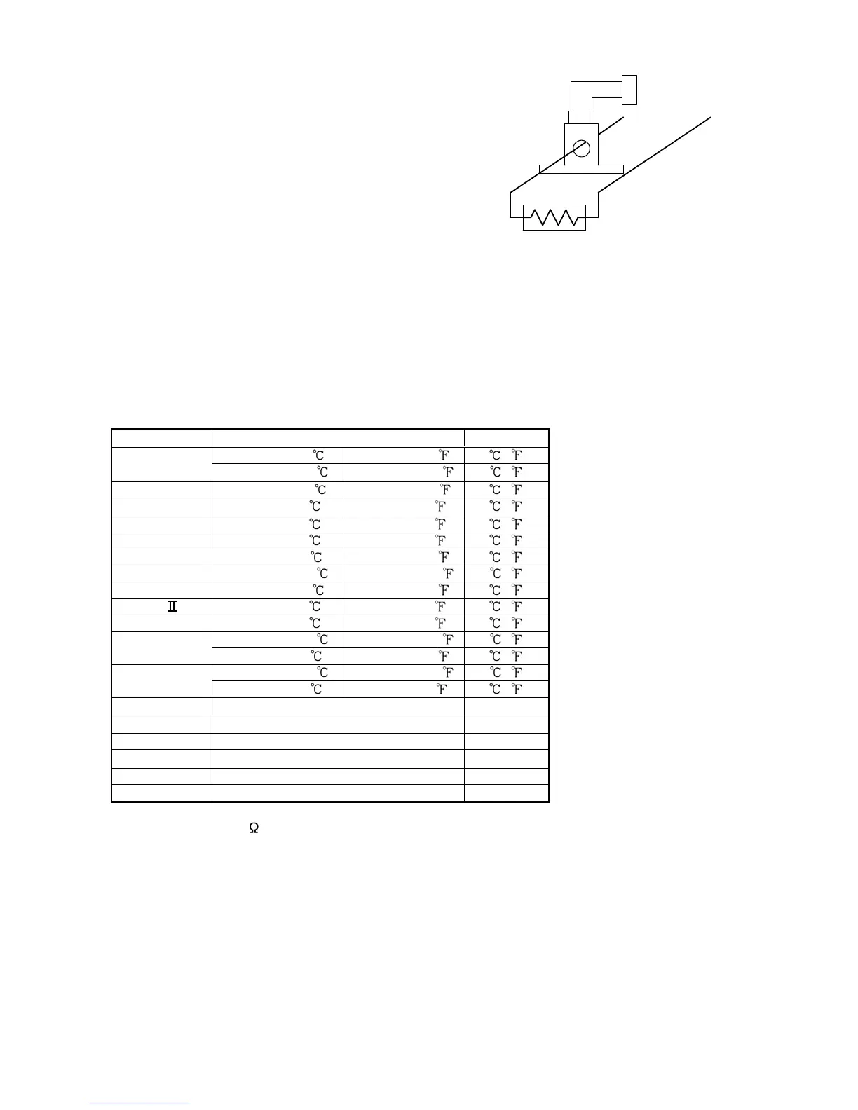
(Table 5-1)
Input Scale range Resolution
-200 to 1370 -320 to 2500 1 ( )
K
-199.9 to 400.0
-199.9 to 750.0 0.1 ( )
J -200 to1000 -320 to1800 1 ( )
R
0 to 1760
0 to 3200 1 ( )
S 0 to 1760 0 to 3200 1 ( )
B 0 to 1820 0 to 3300 1 ( )
E -200 to 800 -320 to 1500 1 ( )
T -199.9 to 400.0 -199.9 to 750.0 0.1 ( )
N -200 to 1300 -320 to 2300 1 ( )
PL- 0 to 1390 0 to 2500 1 ( )
C (W/Re5-26) 0 to 2315 0 to 4200 1 ( )
-199.9 to 850.0 -199.9 to 999.9 0.1 ( )
Pt100
-200 to 850
-300 to 1500 1 ( )
-199.9 to 500.0 -199.9 to 900.0 0.1 ( )
JPt100
-200 to 500
-300 to 900 1 ( )
4 to 20mA DC
-1999 to 9999 *1,*2 1
0 to 20mA DC
-1999 to 9999 *1,*2 1
0 to 1V DC -1999 to 9999 *1 1
0 to 5V DC
-1999 to 9999 *1 1
1 to 5V DC -1999 to 9999 *1 1
0 to 10V DC -1999 to 9999 *1 1
*1: Input range and decimal point place can be changed.
*2: A shunt resistor (50 ) purchased separately must be connected between the input terminals.
CT input socket
Power
supply
Heater
CT
 Loading...