4. Wiring and connection
Warning
Turn the power supplied to the instrument OFF before wiring or checking it.
Working or touching the terminal with the power switched ON may result in Electric
Shock causing severe injury or death.
Caution
• Do not leave wire chips into the DCL-33A series when wiring, because they could cause fire,
malfunction and trouble.
• Insert the connecting cable into the designated connector securely to prevent malfunction,
or it may cause malfunction due to imperfect contact.
• Connect the AC power wiring to the designated terminal as is written in this instruction
manual, or it may burn and damage
the DCL-33A series.
• Tighten the terminal screw with the specified torque, or damage the terminal screw and deform
the case.
• Use thermocouple and compensating lead wire that fit sensor input specification of this unit.
• Use the 3-wire RTD that fits sensor input specification of this unit.
• Do not
confuse the polarity when using DC voltage and current inputs in the case 24V DC is used.
• Keep input wire (Thermocouple, RTD) away from power source and load wire when wiring.
• To prevent the unit from harmful effects of the unexpected level noise, it is recommended that
a surge absorber to be installed between the electromagnetic switch coils.
• This
unit has neither built-in power switch nor fuse. Therfore it is necessary to install them in the
circuit near the external unit.
(Recommended fuse: Rated voltage 250V AC, Rated current 2A, Fuse type: Time-lag fuse)
●
Note
Tighten the terminal screw properly referring to the table below.
Terminal screw Terminal No. Torque
M2.6 1 to 4
Max. 0.5Nm
M2.0 5 to 9
Max. 0.25Nm
●
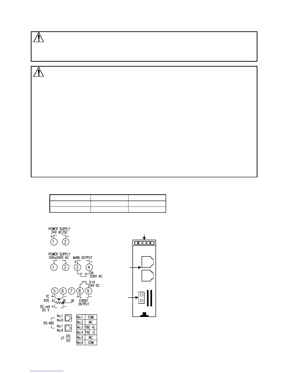
Terminal arrangement
• Power supply
• MAIN OUTPUT: Control output
• EVENT OUTPUT: Outputs when Alarm,
Loop break alarm or Heater burnout
alarm [option] is ON
• RS-485: Serial communication
• TC : Thermocouple
• RTD : Resistance temperature detector
• DC : DC current or DC voltage
(Fig. 4-1)
Lower part of main body
CT input W
Communication
C5 (RS-485)
 Loading...