11. Troubleshooting
If any malfunctions occur, refer to the following items after checking the power supply and wiring.
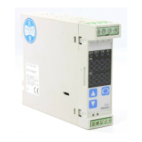
11.1 Indication
Phenomenon Presumed cause and solution
“
” is blinking on the PV
display.
• Sensor (Thermocouple, RTD and DC voltage 0 to 1V DC
input) is burnt out.
Change the sensor for a new one.
• The lead wire of the sensor (Thermocouple, RTD and DC
voltage 0 to 1V DC input ) is not securely connected.
Connect it to the terminal properly.
The indication on the PV display
does not change.
• Check if the input signal source for DC voltage (0 to 10V DC)
and DC current (0 to 20mA DC) is normal.
• Is the lead wire of the sensor DC current (0 to 20mA DC) and
DC voltage (0 to 10V DC) securely connected to the terminal?
Connect the sensor lead wire securely to the instrument
terminal.
“ ” is blinking on the PV
display.
• Check if the input signal source for sensor DC current
(4 to 20mA DC) and DC voltage (1 to 5V DC) input is
normal.
• Is the input signal wire of DC current (4 to 20mA DC) and
DC voltage(1 to 5V DC) securely connected to the terminal
of this instrument?
Connect the input signal wire securely to the terminal of
the instrument.
The indication on the PV display
is abnormal or unstable.
• Is designation of the sensor input correct?
Set the correct sensor input.
• Is the polarity of the sensor input correct?
Wire it correctly.
• Temperature unit (
/ ) is mistaken.
Set the correct unit.
• AC may be leaking into the input of this controller from
thermocouple or the RTD connected to the measured object.
Keep AC from leaking into the input of this controller
from thermocouple or RTD of the measured object.
“ ” is indicated on the
PV display.
• Internal memory is out of order.
Please contact our sales branch or the shop where you
purchased this unit.
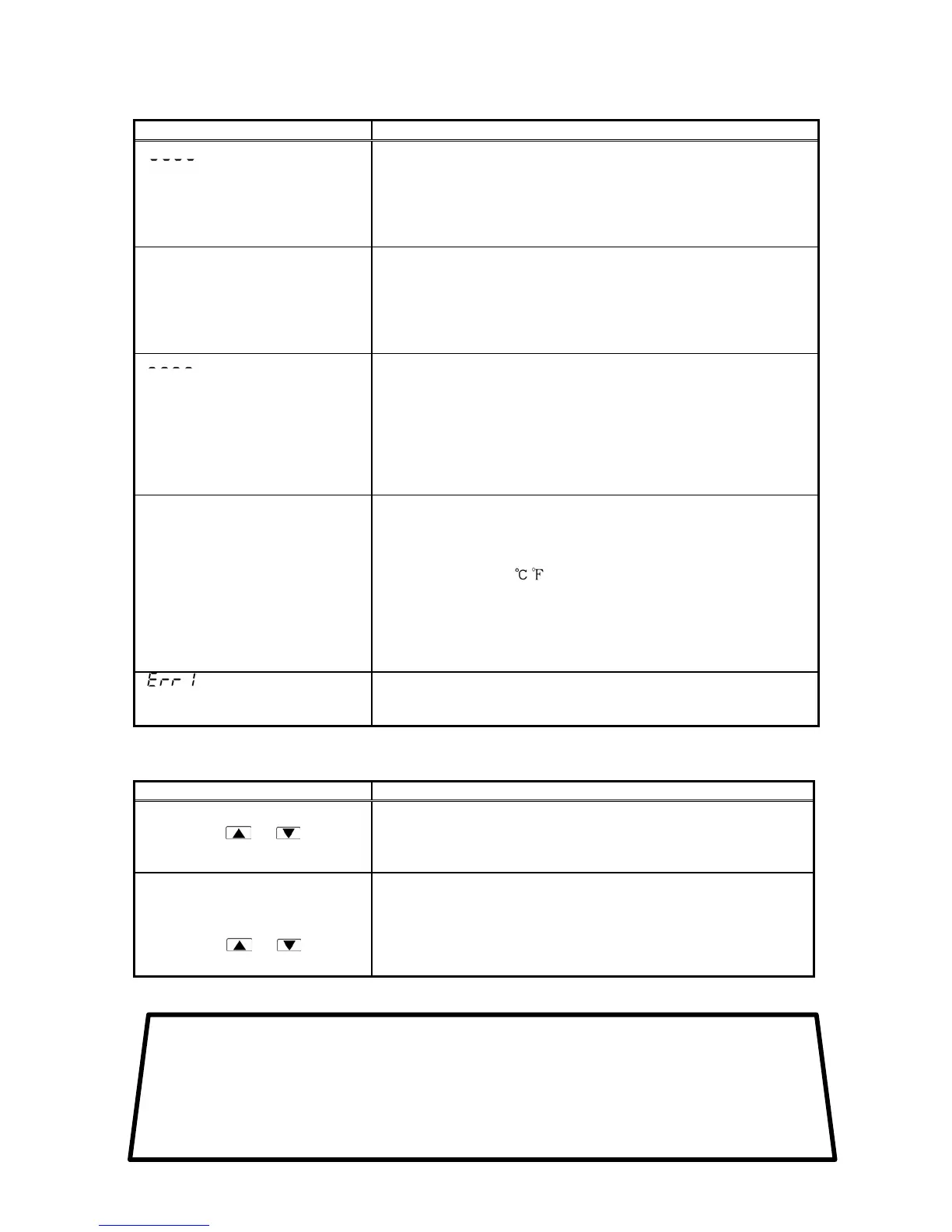
11.2 Key operation
Phenomenon Presumed cause and solution
• Setting values do not change
even if the
or key is
pressed during setting mode
• Mode1 or mode 2 is selected in setting value lock selection.
Cancel the Lock mode.
• PID auto-tuning is performing.
Cancel PID auto-tuning.
• Unable to set the value above
or below scaling high limit or
low limit within the input range
even if the
or key
is pressed.
• The value of scaling high limit setting or low limit setting in
auxiliary function setting mode 2 may be set at the point the
value does not change.
Set the proper value.
• If you have any inquiries, please consult our agency or the shop where you purchased the unit.
No.DCL31E2 Apr. 2002
SHINKO TECHNOS CO.,LTD.
OVERSEAS DIVISION
:
:
:
:
Reg. Office
Mail Address
URL
E-mail
2-48, 1-Chome, Ina, Minoo, Osaka, Japan
P.O.Box 17, Minoo, Osaka, Japan
http://www.shinko-technos.co.jp
overseas@shinko-technos.co.jp
Tel :
Fax:
81-727-21-2781
81-727-24-1760
 Loading...