3
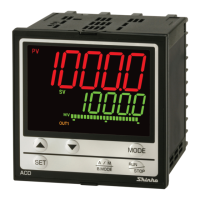
(5) AUTO indicator
The yellow LED lights for Auto limit control action.
(6) TX/RX indicator
The yellow LED lights during Serial communication TX output (sending) (C5 option).
(7) A1 indicator
When Alarm 1 output is ON, the red LED lights.
(8) A2 indicator
When Alarm 2 output is ON, the red LED lights.
(9) Increase key (
)
Increases the numerical value, switches the setting item during the setting mode.
(10) Decrease key (
)
Decreases the numerical value, switches the setting item during the setting mode.
(11) Mode key (
)
Switches setting mode, and registers the set (selected) value.
(12) RESET key (
RESET
)
Resets OUT1 (limit control output).
Notice
When setting the specifications and functions of this controller, connect terminals 2 and 3 for power
source first, then set them referring to Chapter “5. Settings” before performing “3. Mounting to the
control panel” and “4. Wiring”.
3. Mounting to the control panel
3.1 Site selection
Caution
• Use within the following temperature and humidity ranges.
Temperature: 0 to 50 (32 to 122 ), Humidity: 35 to 85%RH (No condensation, no icing)
• When this unit is installed through the control panel, the ambient temperature of this unit must be kept
to under 50
. Otherwise the life of electronic components (especially electrolytic capacitors) will be
shortened.
This instrument is intended to be used under the following environmental conditions
(IEC61010-1): Overvoltage category
, Pollution degree 2
Ensure the mounting location corresponds to the following conditions:
• A minimum of dust, and an absence of corrosive gases
• No flammable, explosive gases
• Few mechanical vibrations or shocks
• No exposure to direct sunlight, an ambient temperature of 0 to 50 (32 to 122 )
that does not change rapidly
• An ambient non-condensing humidity of 35 to 85%RH
• No large capacity electromagnetic switches or cables through which large current flows
• No water, oil or chemicals or where the vapors of these substances can come into direct
contact with the controller

 Loading...