2
1.2 How to read the model label
Model labels are attached to the
case and the inner assembly.
For Heater burnout alarm output,
CT rated current is written in the
bracket.
(1)Model (2)Option, supply voltage (“1” is entered only for 24V AC/DC)
(3)Serial number (Only on inner assembly)
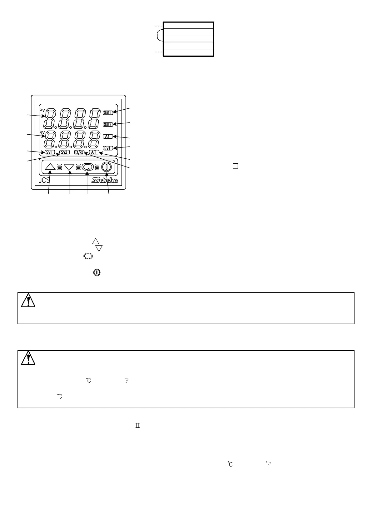
2. Name and functions
(1) PV display : Indicates the PV (process variable) or setting
characters in the setting mode with the red LED.
(2) SV display : Indicates the SV (desired value), MV (manipulated
variable) or each set value in the setting mode
with the green LED.
(3) SV1 indicator : The green LED lights when SV1 is indicated
on the SV display.
(4) SV2 indicator : The yellow LED lights when SV2 is indicated
on the SV display.
(5) OUT1 indicator : When OUT1 is ON, the green LED lights.
(For A/ type, it flashes corresponding to the
manipulated variable in 0.25 second cycles.)
(6) OUT2 indicator : When OUT2 (DT option) is ON, the yellow LED
lights.
(7) A1 indicator : When A1 output is ON, the red LED lights.
(8) EVT indicator : When Event output (A2, LA or W option) is ON,
the red LED lights.
(9) AT indicator : When auto-tuning (AT) or auto-reset is
performing, the yellow LED flashes.
(10) TX/RX indicator : The yellow LED flashes during Serial communication output (transmitting).
(11) Increase key ( ) : Increases the numeric value.
(12) Decrease key ( ) : Decreases the numeric value.
(13) Mode key ( ) : Selects the setting mode or registers the set value.
(By pressing the Mode key, the set value or selected value can be registered)
(14) OUT/OFF key ( ) : The control output ON/OFF function or Auto/Manual control function can be
switched. (To cancel the control output ON/OFF function, press the OUT/OFF
key again for approx. 1 second.)
Notice
When setting the specifications and functions of this controller, connect terminals 1 and 2 for power supply first,
then set them referring to Chapter “5. Setup” before performing “3. Mounting to the control panel” and “4. Wiring”.
3. Mounting to the control panel
3.1 Site selection
Caution
Use within the following temperature and humidity ranges.
Temperature: 0 to 50 (32 to 122 ), Humidity: 35 to 85%RH (No icing, no condensation)
If the JCS-33A is installed through the control panel, the ambient temperature of the JCS-33A must be kept
to under 50 . Otherwise the life of electronic parts (especially electrolytic capacitors) of the JCS-33A will be
shortened.
This instrument is intended to be used under the following environmental conditions
(IEC61010-1): Overvoltage category , Pollution degree 2
Ensure the mounting location corresponds to the following conditions:
• A minimum of dust, and an absence of corrosive gases
• No flammable, explosive gases
• Few mechanical vibrations or shocks
• No exposure to direct sunlight, an ambient temperature of 0 to 50 (32 to 122 )
that does not change rapidly
• An ambient non-condensing humidity of 35 to 85%RH
• No large capacity electromagnetic switches or cables through which large current flows
• No water, oil or chemicals or where the vapors of these substances can come into direct contact
with the controller
(1)
(2)
(3)
(5)
(7)
(8)
(9)
(10)
(11) (12) (13) (14)
(6)
(4)
JCS-33A-R/M
A2
W(20A)
No.
Relay contact output
/Multi-range input
Alarm 2 (A2) output
Heater burnout alarm output (20A)
(1)
(2)
(Model label) (e.g.)
(3)